Preparation method of fuel cell bipolar plate with flow channel

A fuel cell and bipolar plate technology, applied in fuel cells, circuits, electrical components, etc., can solve the problems of complex process flow, uneven conductivity distribution, high cost of metal bipolar plate molds, etc., to simplify the processing process, The effect of shortening processing time and reducing test costs

Active Publication Date: 2019-10-15
CENT SOUTH UNIV
View PDF11 Cites 11 Cited by
  • Summary
  • Abstract
  • Description
  • Claims
  • Application Information

AI Technical Summary

Problems solved by technology

Various bipolar plates have their own advantages and disadvantages: for example, the high-purity graphite plate is processed by high-purity graphite turning and milling and then impregnated, which requires long processing hours and high costs; Mixed and then compression molded
It has the advantages of easy processing and high processing efficiency, but due to the large amount of powder, there are often problems such as uneven conductivity distribution and internal pores;
[0003] The flexible graphite plate is formed by pressing the expanded graphite plate and then impregnated. It has the advantages of good sealing and light weight, but the process is complicated.
The metal bipolar plate has the advantages of easy processing, light weight and small thickness, which is conducive to large-scale production and application, but it needs to be stamped out of the flow channel before it can be treated with surface anti-corrosion coating, resulting in discontinuous coating treatment, thus Makes the price of coating treatment equipment and processing costs very high
If the pre-coating is prepared first and then the flow channel is stamped and formed, the pre-coating may be damaged during the stamping process, and even the slight cracks in the anti-corrosion coating will gradually expand during use, eventually causing metal ions to dissolve or even metal bisecting. plate perforation
And the mold cost of the metal bipolar plate is extremely high

Method used


Image

  • Preparation method of fuel cell bipolar plate with flow channel
  • Preparation method of fuel cell bipolar plate with flow channel
  • Preparation method of fuel cell bipolar plate with flow channel

Examples


Embodiment 1

[0051] In this example, graphite worms, carbon black and phenolic resin are used as conductive paste to make bipolar plates. The preparation method is as follows:

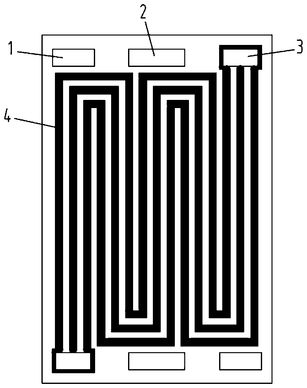
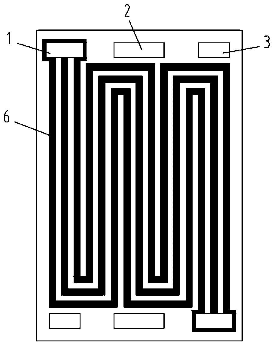
[0052] (1) Use 3D drawing software to draw the patterns of the anode flow field 4, cathode flow field 6 and coolant flow field 5 printed on the metal plate;

[0053] (2) Disperse graphite worms, carbon black, and phenolic resin in a solvent at a solid content ratio of 5:3:2 to obtain a uniform mixture and then dry it;

[0054] (3) The 3D printer moves the print head according to the printing path, draws several conductive paste tracks according to a specific pattern on one side of the first metal plate, and solidifies the conductive paste by heating to form a flow channel protruding from the surface of the metal plate Ridge; several flow channel ridges constitute a single-sided anode flow field 4 according to a specific pattern;

[0055] (4) The 3D printer moves the print head according to the printing path, draws...

Embodiment 2

[0059] In this embodiment, carbon black, carbon nanofibers, and phenolic resin are used as conductive pastes to make bipolar plates. The preparation method is as follows:

[0060] (1) Use 3D drawing software to draw the patterns of the anode flow field 4, cathode flow field 6 and coolant flow field 5 printed on the metal plate;

[0061] (2) Disperse carbon black, carbon nanofibers, and phenolic resin in a solvent at a solid content ratio of 6:2:2 to obtain a uniform mixture and then dry it;

[0062] (3) The 3D printer moves the print head according to the printing path, draws several conductive paste tracks according to a specific pattern on one side of the first metal plate, and solidifies the conductive paste by heating to form a flow channel protruding from the surface of the metal plate Ridge; several flow channel ridges constitute a single-sided anode flow field 4 according to a specific pattern;

[0063] (4) The 3D printer moves the print head according to the printing ...

Embodiment 3

[0067] In this example, titanium nitride and phenolic resin are used as conductive paste to make bipolar plates. The preparation method is as follows:

[0068] (1) Use 3D drawing software to draw the patterns of the anode flow field 4, cathode flow field 6 and coolant flow field 5 printed on the metal plate;

[0069] (2) Disperse titanium nitride and phenolic resin in a solvent at a solid content ratio of 9:1 to obtain a uniform mixture and then dry it;

[0070] (3) The 3D printer moves the print head according to the printing path, draws several conductive paste tracks according to a specific pattern on one side of the first metal plate, and solidifies the conductive paste by heating to form a flow channel protruding from the surface of the metal plate Ridge; several flow channel ridges constitute a single-sided anode flow field 4 according to a specific pattern;

[0071] (4) The 3D printer moves the print head according to the printing path, draws several conductive paste t...


PUM

PropertyMeasurementUnit
Heightaaaaaaaaaa
Widthaaaaaaaaaa

Abstract

The invention discloses a preparation method of a fuel cell bipolar plate with a flow channel, which includes the following steps: drawing an anode flow field pattern, a cathode flow field pattern anda coolant flow field pattern through 3D drawing; applying conductive paste to a surface of one metal plate through 3D printing or injection molding to form an anode (or cathode) flow field, and applying conductive paste to the two surfaces of the other metal plate through 3D printing or injection molding to form a cathode (or anode) flow field and a coolant flow field; and aligning and fitting the smooth surface of the metal plate with the anode (or cathode) flow field formed thereon with the surface of the metal plate with the coolant flow field formed thereon, and carrying out welding and sealing to form a bipolar plate with a flow channel. The method combines the processing advantages of a metal bipolar plate and a molded composite graphite plate, reduces the cost of mold opening and the difficulty of processing, and has the advantages of short construction period and low cost especially for frequent modification of the design of the flow channel.

Description

technical field [0001] The invention relates to a method for preparing a bipolar plate of a fuel cell, in particular to a method for preparing a bipolar plate of a fuel cell containing flow channels, and belongs to the technical field of fuel cells. Background technique [0002] Fuel cells have the advantages of high energy conversion efficiency, high energy density, environmental protection and pollution-free, and are regarded as the ultimate energy source in the future. The cost of bipolar plates accounts for more than 30% of the cost of a fuel cell stack. Traditional fuel cell bipolar plates usually include high-purity graphite plates, molded composite graphite plates, flexible graphite plates, metal bipolar plates, and the like. Various bipolar plates have their own advantages and disadvantages: for example, the high-purity graphite plate is processed by high-purity graphite turning and milling and then impregnated, which takes a long time and high cost; the molded comp...

Claims


Application Information

Patent Timeline
IPC IPC(8): H01M8/0258H01M8/0267
CPCH01M8/0258H01M8/0267Y02P70/50Y02E60/50H01M8/0202
Inventor 谢志勇熊子昂梁伊丽
Owner CENT SOUTH UNIV
Why Eureka
Try Eureka