
Integrated oil distribution system with pipelines in pump room being centralized

A technology of oil system and pump room, which is applied in the field of pipeline integrated oil separation system in centralized pump room, which can solve problems such as failure to meet food safety requirements, cumbersome confirmation, oil leakage, etc., to reduce the probability of oil leakage and pollution, Improve safety and reliability, and facilitate installation and maintenance

Active Publication Date: 2019-09-10
JIALI GRAIN & OIL TIANJIN
View PDF12 Cites 0 Cited by
  • Summary
  • Abstract
  • Description
  • Claims
  • Application Information

AI Technical Summary

Problems solved by technology

The number of storage tanks is far greater than the number of workshops, and it is impossible to use dedicated pipes. The storage tank connections in the pump room need to be connected to the corresponding pump ports with hoses or oil distribution bags
Disadvantages of the existing technology: use a hose to connect the pump and the storage tank, the pressure in the pipeline is not reduced during disassembly, and the hose will burst and hurt people; use a hose to connect the pump and the storage tank, the oil will leak out when the hose is switched, and the soft The pipe is polluted, which does not meet the food safety requirements; using the oil separation bag to connect the pump and the storage tank, the confirmation is cumbersome during dynamic switching, and accidents of oil contamination are prone to occur; the use of the oil separation bag to connect the pump and the storage tank has a relatively single function, which is suitable for Oil type and less dynamic tank farm operation mode

Method used


Image

  • Integrated oil distribution system with pipelines in pump room being centralized
  • Integrated oil distribution system with pipelines in pump room being centralized
  • Integrated oil distribution system with pipelines in pump room being centralized

Examples


Embodiment Construction

[0021] It should be noted that, in the case of no conflict, the embodiments of the present invention and the features in the embodiments can be combined with each other.

[0022] In describing the present invention, it should be understood that the terms "center", "longitudinal", "transverse", "upper", "lower", "front", "rear", "left", "right", The orientations or positional relationships indicated by "vertical", "horizontal", "top", "bottom", "inner", "outer", etc. are based on the orientation or positional relationships shown in the drawings, and are only for the convenience of describing the present invention Creation and simplification of description, rather than indicating or implying that the device or element referred to must have a specific orientation, be constructed and operate in a specific orientation, and therefore should not be construed as limiting the invention. In addition, the terms "first", "second", etc. are used for descriptive purposes only, and should no...


PUM


Abstract

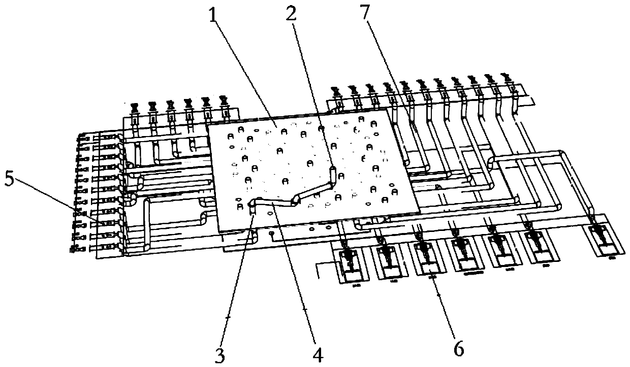
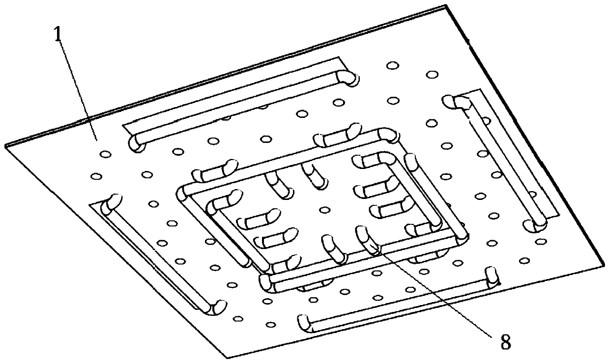
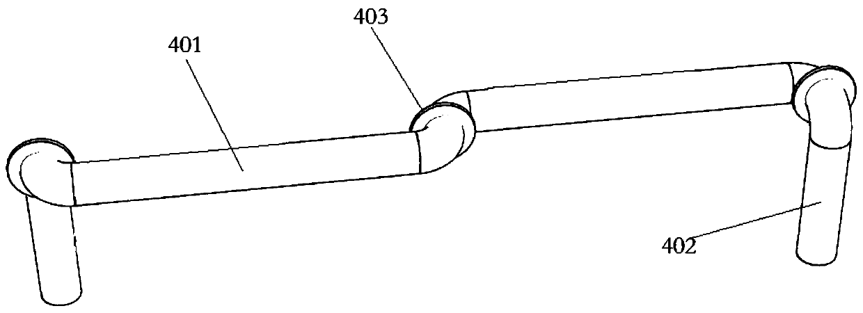
The invention provides an integrated oil distribution system with pipelines in a pump room being centralized. The integrated oil distribution system comprises a horizontal oil distribution plate whichis arranged in the pump room and a storage tank for storing oil which is arranged on the oil distribution plate; the storage tank is arranged at the periphery of the oil distribution plate and is connected with oil supply equipment outside the oil distribution plate through external connection pipelines; an oil pump is arranged on the oil distribution plate; the oil inlet end of the oil pump is connected with the storage tank through an adapter pipe fitting; the oil outlet end of the oil pump is connected with oil outlet equipment of the pump room through the external connection pipelines; the oil distribution plate is internally provided with embedded pipe fittings; and connecting joints for connecting with the adapter pipe fitting are arranged at the two ends of the embedded pipe fittings. By concentrating the external connection pipelines on the oil distribution plate, the problem of winding and pollution caused by a too long hose in a hose oil distribution system is solved, and the safety and reliability of the oil distribution system are improved.

Description

technical field [0001] The invention belongs to the fields of grain, oil and oil chemical industry, and in particular relates to a pipeline integrated oil separation system in a centralized pump room. Background technique [0002] In the grain, oil and oleochemical industry, the oil is connected from the storage tank to the pump room through pipelines, and the oil pump in the pump room is used to provide power to transport to the workshop for processing. After the workshop is processed, the oil is returned to the (semi) finished product tank. The number of storage tanks is far greater than the number of workshops, and special pipes cannot be dedicated. The storage tank connections in the pump room need to be connected to the corresponding pump ports with hoses or oil distribution bags. Disadvantages of the existing technology: use a hose to connect the pump and the storage tank, the pressure in the pipeline is not reduced during disassembly, and the hose will burst and hurt ...

Claims


Application Information

Patent Timeline
Patent Type & Authority Applications(China)
IPC IPC(8): B67D7/02B67D7/38B67D7/06
CPCB67D7/02B67D7/06B67D7/38
Inventor 荣秀峰魏连斌赵旺赵祥竣
Owner JIALI GRAIN & OIL TIANJIN
Learn More