Upper swinging type lens grinding machine

A grinding machine and grinding mechanism technology, applied in grinding machine tools, grinding devices, grinding tools, etc., can solve the problems of easy occurrence of scrapped products, low work efficiency, difficult grinding process operation, etc., so as to improve work efficiency and grinding efficiency. , Improve the effect of grinding uniformity

Pending Publication Date: 2019-08-23
福州研达自动化有限公司
View PDF0 Cites 4 Cited by
  • Summary
  • Abstract
  • Description
  • Claims
  • Application Information

AI Technical Summary

Problems solved by technology

After the blank is cut and ground, its basic size and surface finish have been formed, but it still cannot meet the customer's optical requirements, and the grinding process must be carried out. Grinding is the most important process to obtain an optical surface.
Traditional manual grinding has low work efficiency and cannot meet the high-efficiency production requirements, and the operation of the grinding process is difficult and prone to scrapped products

Method used


Image

  • Upper swinging type lens grinding machine
  • Upper swinging type lens grinding machine
  • Upper swinging type lens grinding machine

Examples


Embodiment 1

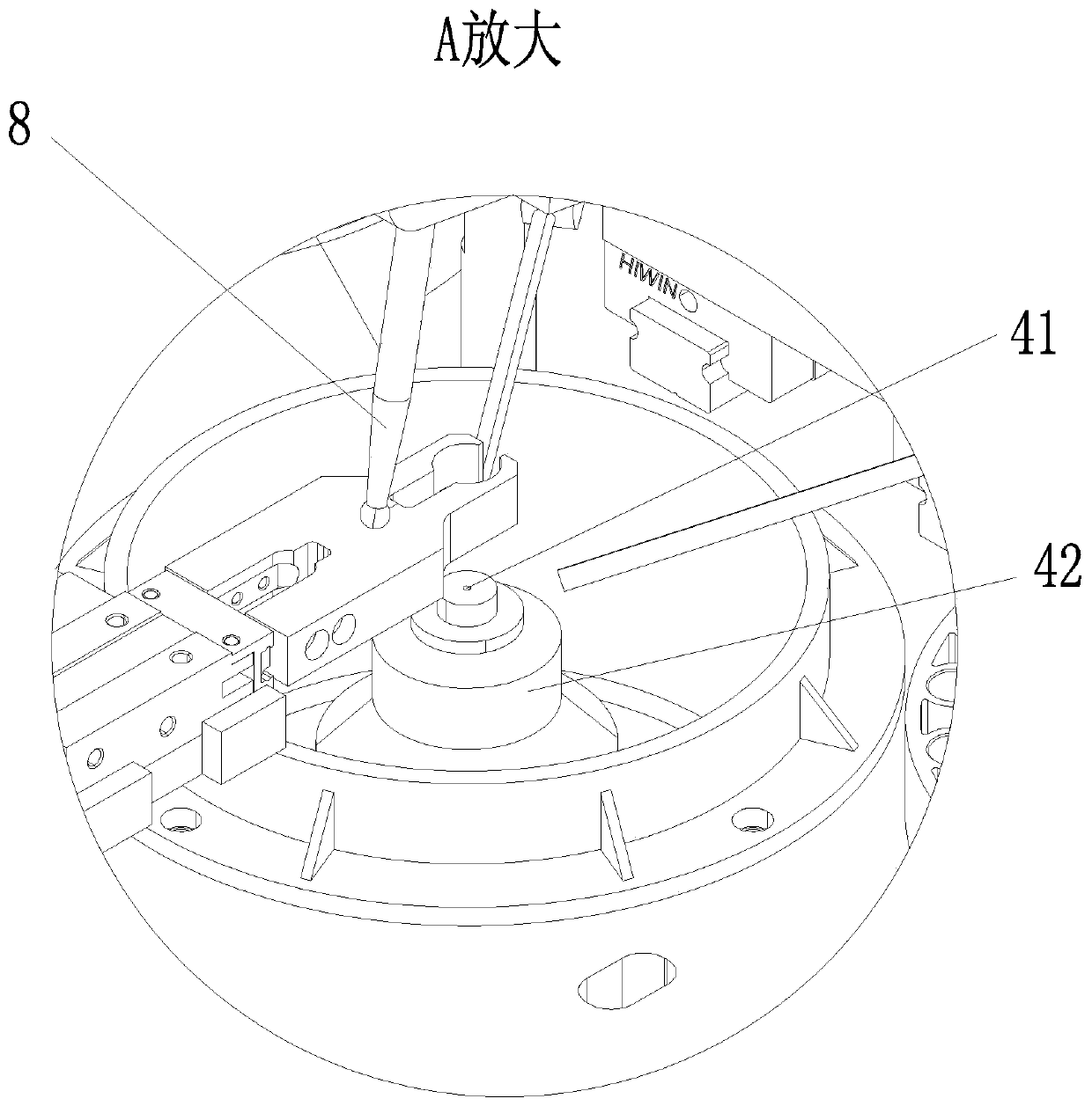
[0063] Such as Figure 1-17As shown, a kind of upper pendulum lens grinding machine of the present invention is characterized in that: comprise more than one group of complete grinding machine 1, each group of grinding complete machine 1 comprises frame 2, is respectively installed on the frame 2 and is used for processing The grinding mechanism 4 for grinding the material 3, the material storage mechanism 5 arranged on one lateral side of the grinding mechanism 4 for placing the material 3 to be processed, and the material storage mechanism 5 arranged on the other lateral side of the grinding mechanism 4 for storing finished materials 3, the finished product storage mechanism 6, the frame 2 is also provided with a material for transferring the material 3 to be processed on the material storage mechanism 5 to the grinding mechanism 4 and transferring the finished material 3 on the grinding mechanism 4 to the finished product The material transfer mechanism 7 on the storage mec...

Embodiment 2

[0089] Such as Figure 18 As shown, the difference between the present embodiment and the first embodiment is that the complete grinding machine 1 is set up sequentially according to the sequence of the spherical lens processing process, and the combined design of multiple processes can realize multiple processes such as roughing, polishing, and fine grinding at the same time. conduct.


PUM


Abstract

The invention relates to an upper swinging type lens grinding machine. One or more grinding complete machines are included. Each grinding complete machine comprises a rack, wherein the rack is provided with a grinding mechanism for grinding to-be-machined materials, a material storage mechanism arranged on one transverse side of the grinding mechanism, and a finished product storage mechanism arranged on the other transverse side of the grinding mechanism, and the rack is further provided with a material transferring mechanism. The materials include a material clamp and a material body arranged on the material clamp, wherein the material to-be-machined face at the bottom of the material body is exposed out of the bottom of the material clamp. Each grinding mechanism comprises a grinding groove, a grinding rotation driving mechanism, a material pressing bar arranged above the grinding groove, and a swing arm mechanism which is used for clamping the material pressing bar and driving thematerial pressing bar to swing around the contact point where the material pressing bar and the materials are in contact in the longitudinal direction of the grinding groove in a reciprocating manner.The upper swinging type lens grinding machine can replace manual grinding, the grinding efficiency of the grinding machine is high, operation is simple, and the quality of ground finished products isgood.

Description

technical field [0001] The invention relates to the field of lens grinding equipment, in particular to a swing-up lens grinding machine. Background technique [0002] The processing flow of the spherical lens includes: cutting, grinding, grinding, and cleaning. After cutting and grinding, the basic size and surface finish of the billet have been formed, but it still cannot meet the customer's optical requirements, and the grinding process must be carried out. Grinding is the most important process to obtain an optical surface. Traditional manual grinding has low work efficiency and cannot meet the high-efficiency production requirements. Moreover, the operation of the grinding process is difficult and scrapped products are prone to occur. Contents of the invention [0003] The object of the present invention is to provide a swing-up lens grinder, which can replace manual grinding, and has high grinding efficiency, simple operation, and good quality of finished products af...

Claims


Application Information

Patent Timeline
IPC IPC(8): B24B13/00B24B37/025B24B37/11B24B37/27B24B37/34B24B47/12
CPCB24B13/00B24B37/025B24B37/11B24B37/27B24B37/34B24B37/345B24B47/12
Inventor 黄朝峰林孝平方志毅余朝锋雷海涛许少欣翁齐举崔鑫
Owner 福州研达自动化有限公司
Why Eureka
Try Eureka