
Speed reducer input shaft machining process

A technology of processing technology and input shaft, which is applied in the field of processing technology of the input shaft of the reducer, can solve the problems that the hardness and strength of the inner spline 2 cannot meet the requirements, affect the product quality, and the fracture of the inner spline 2, etc., and achieve reliable clamping Durability, good wear resistance, and the effect of reducing deformation

Inactive Publication Date: 2019-08-20
昆山赫斯顿精密五金机械有限公司
View PDF10 Cites 4 Cited by
  • Summary
  • Abstract
  • Description
  • Claims
  • Application Information

AI Technical Summary

Problems solved by technology

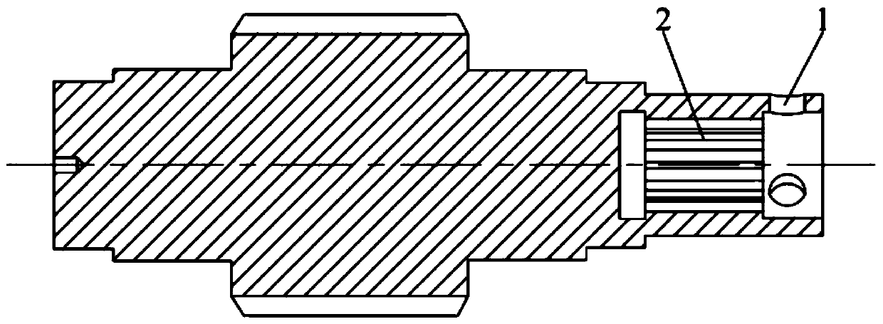
Due to the setting of the pin hole 1, when the pin hole 1 is processed, the inner spline 2 has a tendency to be deformed and the hardness and strength of the inner spline 2 cannot meet the requirements, which affects the quality of the product. break, dangerous

Method used


Image

  • Speed reducer input shaft machining process
  • Speed reducer input shaft machining process

Examples


Embodiment Construction

[0031] The technical solutions of the present invention will be further described below in conjunction with the accompanying drawings and through specific implementation methods.

[0032] figure 1 It is the input shaft processed in the embodiment of the present invention, and the input shaft is provided with internal splines 2 and pin holes 1 arranged radially along the input shaft.

[0033] In order to reduce the deformation of the input shaft, increase the hardness of the inner spline 2, and further improve the quality and service life of the input shaft, the present invention provides a processing technology for the input shaft of a reducer, which includes the following steps:

[0034] 1) For blanking, forgings are selected for blanks. Forgings have greater toughness and rigidity, and are more economical. The blank material is 20CrMnTi, 20CrMnTi has good machinability, small processing deformation, good fatigue resistance, good machinability after normalizing, and is conve...


PUM


Abstract

The invention discloses a speed reducer input shaft machining process, and belongs to the technical field of shaft machining. The speed reducer input shaft machining process comprises the steps of unloading, normalization, roughing, carbonitriding of the surfaces of blanks, heat treatment, high-frequency annealing of pin hole areas by using high-frequency equipment, finishing and warehousing; theroughing procedure is reasonably arranged; in carbonitriding, the blanks are strongly permeated by 4.5-5.5 h at 864-876 DEG C, and the dispersion time is 0.8-1.2 h. In the heat treatment, the quenching temperature is 846-857 DEG C, and the time is 0.45-0.53 h; the tempering temperature is 180-210 DEG C, and the time is 1.8-2.2 h; and the finishing comprises grinding of outer circles and grinding teeth of all shaft sections. Through reasonable arrangement of the machining process, the deformation of inner splines is reduced, and the hardness and the strength of the inner splines are improved.

Description

technical field [0001] The invention relates to the technical field of shaft processing, in particular to a processing technology for an input shaft of a reducer. Background technique [0002] As one of the key parts of the reducer, the input shaft not only transmits torque, but also bears large bending stress, contact stress and certain impact. Such as figure 1 The input shaft of a reducer is shown, the hole of the input shaft is provided with an internal spline 2, along the radial direction of the input shaft is provided with a pin hole 1 for positioning the output shaft of the power device, there are three pin holes 1 and they are evenly distributed On the circumference of the input shaft, the power device transmits the power to the reducer through the inner spline 2 and the pin hole 1, which can improve the service life of the input shaft and is used to transmit relatively large power. [0003] The traditional processing process of the input shaft is: blanking→normaliz...

Claims


Application Information

Patent Timeline
Patent Type & Authority Applications(China)
IPC IPC(8): B23P15/14
CPCB23P15/14
Inventor 张善衡乔艳春张明扬
Owner 昆山赫斯顿精密五金机械有限公司
Learn More