
Anti-impact structure optimized design method

An optimized design, impact-resistant technology, applied in clothing, helmets, helmet covers, etc., can solve problems such as increasing the overall structural mass, center of mass offset, component or human body damage, etc.

Inactive Publication Date: 2019-08-02
BEIHANG UNIV
View PDF7 Cites 0 Cited by
  • Summary
  • Abstract
  • Description
  • Claims
  • Application Information

AI Technical Summary

Problems solved by technology

First of all, in the layout of the protective structure, the impact characteristics of the protective parts are not considered, and the method of uniform distribution is often used. This method is designed to protect the maximum impact. Although it can protect the protective equipment, it also increases the protection. The use of structures and materials, and unnecessary structural arrangements increase the quality of the overall structure and cause the center of mass to shift. The increase in mass and the shift of the center of mass will not only seriously affect the protection effect, but will even cause serious damage to the protected parts or human body. additional risk of injury
Especially in pilot helmets, under high-speed overload, the increase in helmet mass and the offset of the center of mass will cause excessive fatigue or even damage to the pilot's helmet, increasing the risk of accidents
Secondly, in order to increase the impact time and the energy absorption of the structure, materials and structures that can undergo large deformation are generally used in the existing impact protection, such as polystyrene foam is used as the buffer layer of the helmet in the general helmet design, which is of great importance. Increases the size and volume of the structure, and excessive deformation will also affect the distribution of the center of mass of the impact structure, thereby also reducing the stability of the protective equipment

Method used

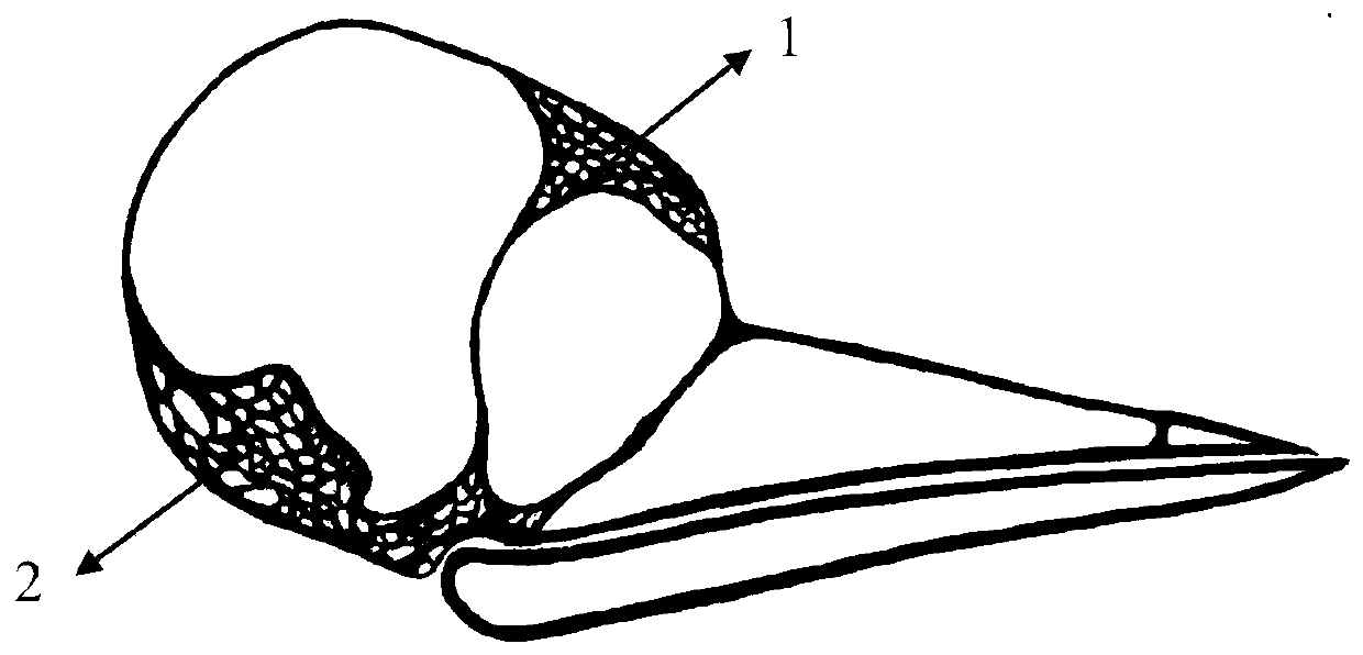
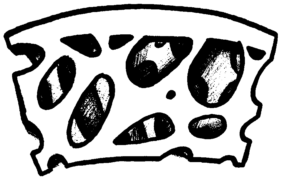
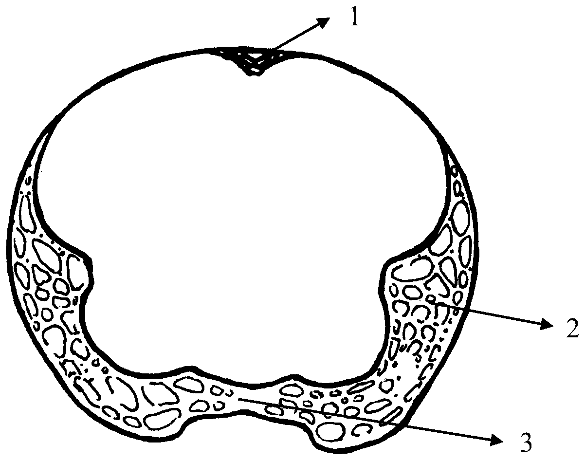

Image

  • Anti-impact structure optimized design method
  • Anti-impact structure optimized design method
  • Anti-impact structure optimized design method

Examples


Embodiment Construction

[0018] In order to present the purpose and technical solution of the present invention more clearly, the application of this method will be further described in detail in conjunction with the design of a certain impact-resistant equipment:

[0019] The impact resistance design of protective equipment is mainly carried out on the microscopic parameter design and distribution optimization of its internal structure; by optimizing the internal microstructural parameters and the distribution position of the structure, the overall impact resistance of the protective equipment is increased, and the The utilization rate of materials reduces the quality of equipment and improves the stability of equipment.

[0020] First of all, aiming at the design of the microscopic parameters of the internal structure of the protective equipment, combined with the porous morphology and microstructural characteristics of the cancellous bone in the woodpecker skull, the structural parameters such as th...


PUM


Abstract

The invention discloses an anti-impact structure optimized design method, which is based on a woodpecker head anti-impact principle. The method is characterized in that by using the structure characteristic of a woodpecker that the cancellous bone in the skull is similar to the plate shape and the characteristic of nonuniform distribution of the cancellous bone in the skull, the structure microscopic parameter design and the protection requirements of different positions of protection equipment are combined, the structure design and distribution is formed in the whole protection equipment; ina position with great impact, the mass center position of the protection equipment is regulated through controlling the structure microscopic parameter, increasing the structure intensity and improving the anti-impact performance and deformation resistance capability via the structure arrangement and distribution. The impact effect is ensured; meanwhile, the material utilization rate is improved;the mass of protection equipment is reduced; the stability of the protection equipment is improved. The method can be applied to the helmet design of an athlete and a pilot and the design of other protection equipment. The method does not relate to the concrete material of the anti-impact structure and the manufacturing process, and does not relates to the concrete mode of the structure distribution.

Description

technical field [0001] The invention relates to the field of impact-resistant structure design and the field of bionics, in particular to an optimal design method of an impact-resistant structure based on the impact-resistant principle of a woodpecker head. Background technique [0002] Collisions and impacts are very common phenomena in everyday life. In the field of transportation, collisions are almost inevitable, and such collisions are very easy to cause damage to passengers; in the field of aerospace, pilots will also be constantly collided under various load conditions, which will seriously threaten flight safety; The impact protection of the head and brain is also an important issue in sports competitions where violent collisions occur. In recent decades, people have carried out a series of researches on impact protection. In order to reduce human body injury or component damage caused by various collisions, impact-resistant equipment is generally used to protect t...

Claims


Application Information

Patent Timeline
IPC IPC(8): A42B3/06
CPCA42B3/06
Inventor 樊瑜波王丽珍刘景龙姚艳
Owner BEIHANG UNIV
Learn More