Bridge large-diameter precast concrete pipe column foundation and construction method thereof

A prefabricated concrete and pipe column foundation technology, which is applied in basic structural engineering, bridges, bridge construction, etc., can solve the problems of difficult to guarantee the quality of underwater concrete pouring, large consumption of structural construction materials, poor adaptability to stratum deformation, etc. The benefits and social benefits are obvious, the load is increased, and the horizontal bearing capacity is large.

Pending Publication Date: 2019-07-09
CCCC SECOND HARBOR ENG +1
View PDF10 Cites 1 Cited by
  • Summary
  • Abstract
  • Description
  • Claims
  • Application Information

AI Technical Summary

Problems solved by technology

[0004] However, the structural form of the urban bridge substructure "bored pile + cap + pier column" has poor adaptability to ground deformation, and the appearance of the road surface is seriously affected after settlement. The large cap structure size affects the passage space under the bridge, and the foundation adopts cast-in-situ pile There are problems such as large consumption of structural construction materials, slow hole forming speed, long construction period, and difficult construction quality control; the construction technology of bored piles also has certain defects, and the construction mud and drilling slag are harmful to the surrounding vegetation soil, surface water and Groundwater causes serious pollution, there is a lot of construction noise during construction, the quality of underwater concrete pouring is difficult to guarantee, and the degree of prefabrication is low.

Method used


Image

  • Bridge large-diameter precast concrete pipe column foundation and construction method thereof
  • Bridge large-diameter precast concrete pipe column foundation and construction method thereof
  • Bridge large-diameter precast concrete pipe column foundation and construction method thereof

Examples


Embodiment Construction

[0044] The present invention will be further described in detail below in conjunction with the accompanying drawings, so that those skilled in the art can implement it with reference to the description.

[0045] It should be noted that the experimental methods described in the following embodiments, unless otherwise specified, are conventional methods, and the reagents and materials, if not otherwise specified, can be obtained from commercial sources; in the description of the present invention, The terms "landscape", "portrait", "top", "bottom", "front", "rear", "left", "right", "vertical", "horizontal", "top", "bottom", The orientation or positional relationship indicated by "inner", "outer", etc. is based on the orientation or positional relationship shown in the drawings, which is only for the convenience of describing the present invention and simplifying the description, and does not indicate or imply that the referred device or element must have Certain orientations, co...


PUM


Abstract

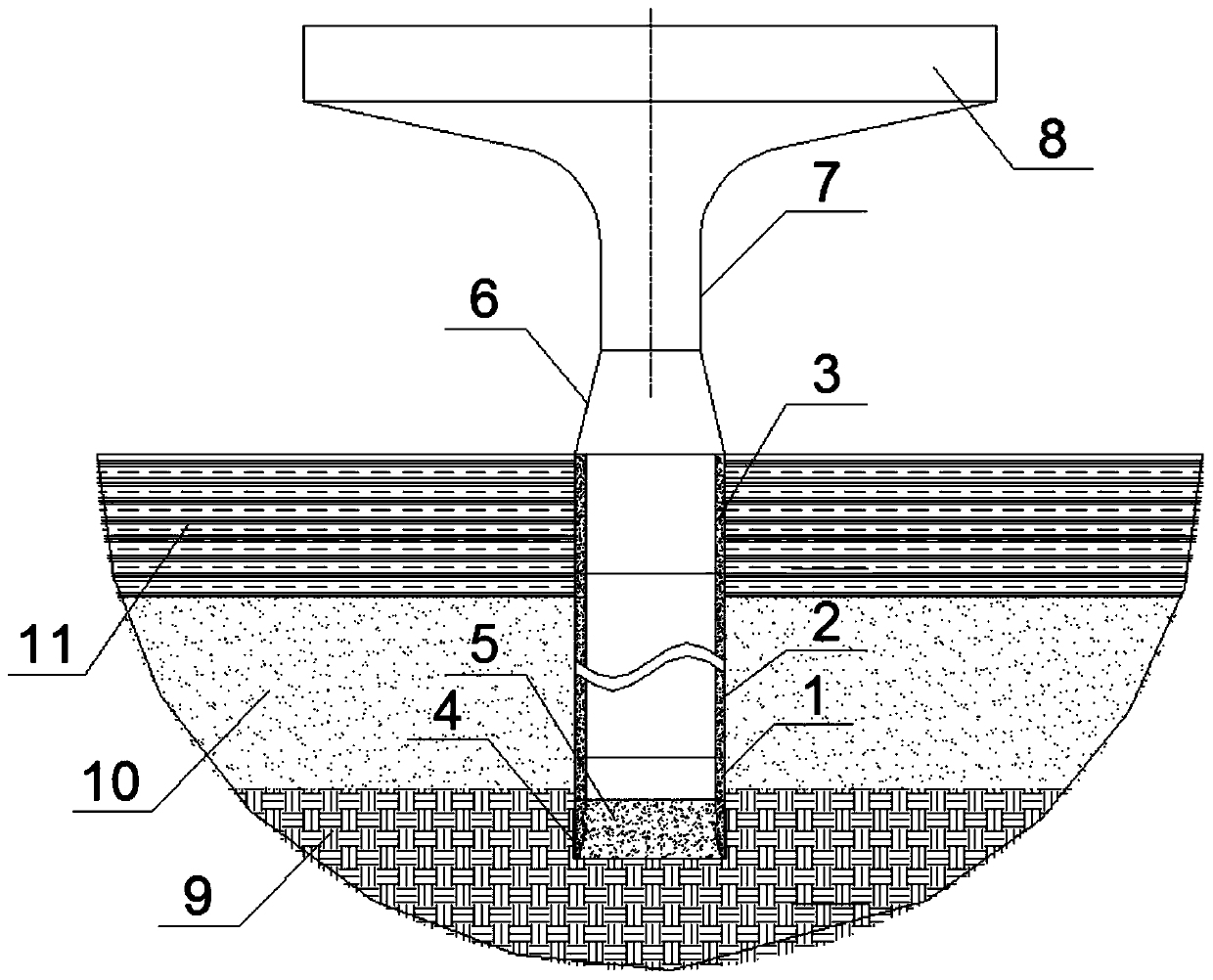
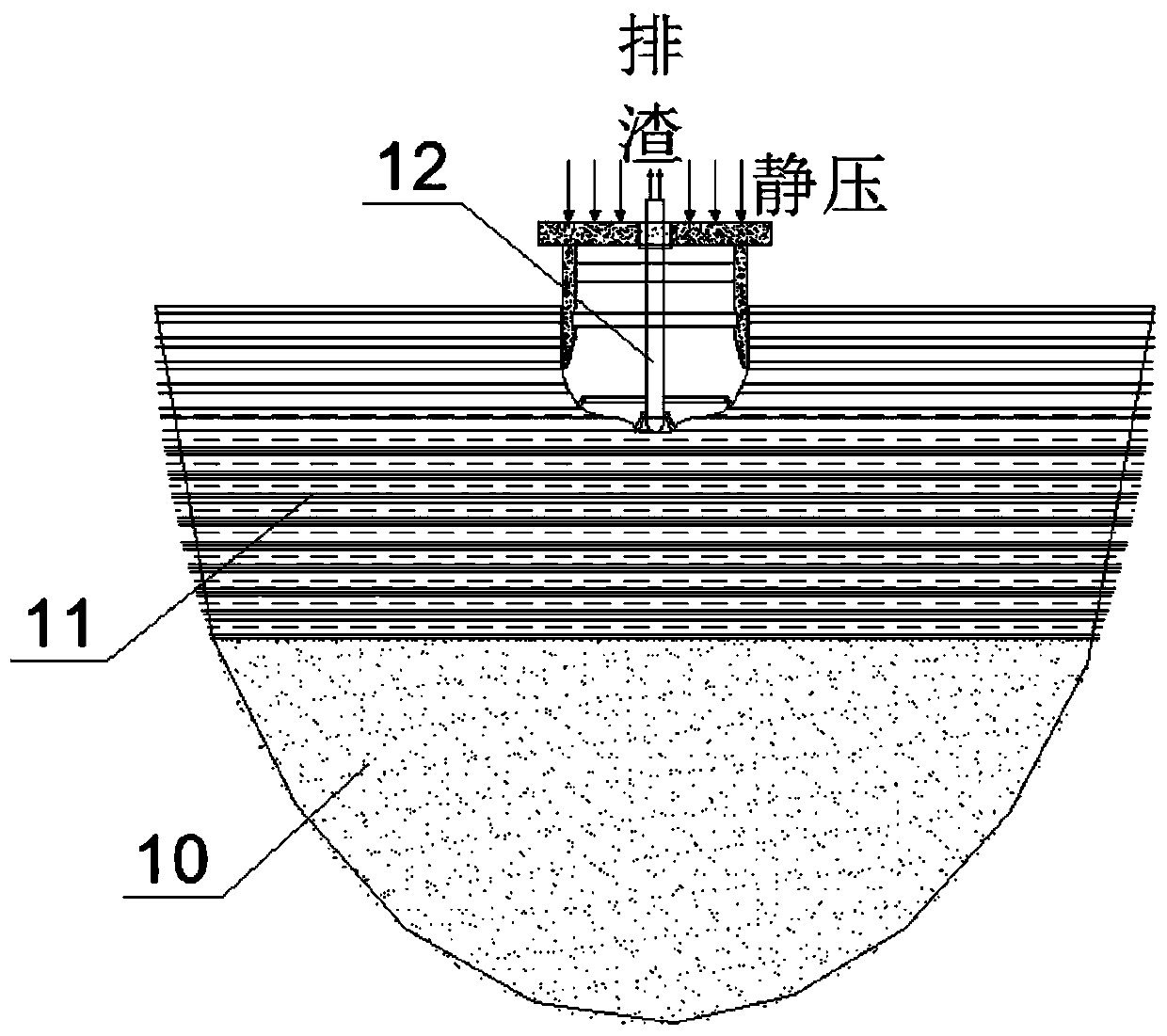
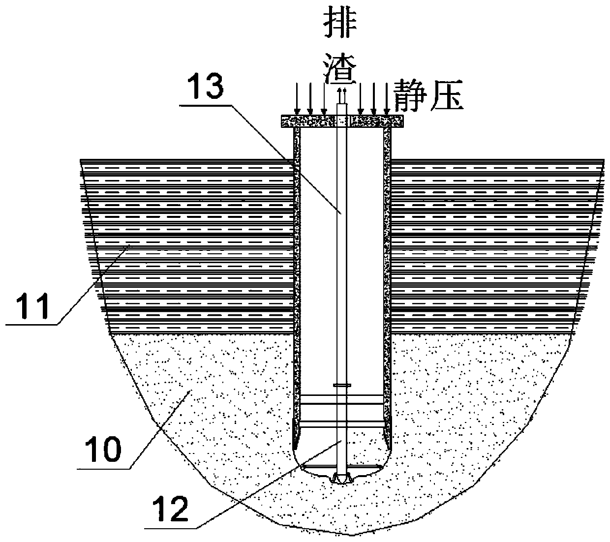
The invention discloses a bridge large-diameter precast concrete pipe column foundation. The bridge large-diameter precast concrete pipe column foundation comprises a pipe column body and a connectingsection, wherein the pipe column body comprises a pipe column bottom section, a multiple standard pipe column sections and a pipe column top section which are connected in sequence from bottom to top, the pipe column body is of a hollow sleeve structure and is vertically located in a soil layer, and the bottom of the pipe column body is sealed through bottom sealing concrete; the connecting section is located on the soil layer and is of a solid structure, the lower end of the connecting section is connected with the pipe column top section, and the top end of the connecting section is connected with a pier column. The invention also discloses a construction method for the bridge large-diameter precast concrete pipe column foundation. The prefabricated construction of the bridge pipe column foundation is completed by prefabricating the large-diameter pipe column and adopting an on-site static pressure method cooperating with small cutter suction dredging equipment. The pipe column foundation does not need a bearing platform after construction, so that the cost is reduced, the construction cycle is shortened, the prefabricated assembly degree is high, and the application prospect isbroad.

Description

technical field [0001] The invention relates to the technical field of bridge foundation construction structures. More specifically, the present invention relates to a large-diameter prefabricated concrete pipe column foundation for land bridges and a construction method thereof. Background technique [0002] With the rapid development of my country's economy, the demand for urban transportation is growing rapidly. Municipal bridges are more and more widely used in urban construction because they can greatly improve traffic capacity and alleviate urban congestion. The substructure of municipal bridges usually adopts the structural form of "bored piles + caps + pier columns". Mature, safe and reliable construction process, etc., are currently widely used in bridge foundations. [0003] At present, there are mainly two common construction techniques for cast-in-situ piles. The first method is the mud retaining method, and piles are formed by drilling concrete (impact drill,...

Claims


Application Information

Patent Timeline
Patent Type & Authority Applications(China)
IPC IPC(8): E01D21/00E02D27/42
CPCE01D21/00E02D27/42
Inventor 翟世鸿吴启和柯杰韩鹏鹏徐杰邱敏万猛张磊
Owner CCCC SECOND HARBOR ENG
Why Eureka
Try Eureka