Rainbow-shaped gate

A gate, rainbow technology, applied in water conservancy projects, marine engineering, coastline protection and other directions, can solve the problems of easy deformation in the middle of the gate, difficult installation, siltation and other problems, to achieve a more peculiar and spectacular shape, improve the strength of the gate, and avoid corrosion.

Inactive Publication Date: 2017-06-20
YANGZHOU CHUMEN ELECTROMECHANICAL DEVICES MFG
View PDF4 Cites 4 Cited by
  • Summary
  • Abstract
  • Description
  • Claims
  • Application Information

AI Technical Summary

Problems solved by technology

When the gate is working, the gear or fan gear rotates, thereby driving the bottom shaft to rotate. When the gate leaf is upright, it will store water, and when the gate leaf is lying down, it will flood. The surface of the gate is constantly impacted by the river water. If the width of the river channel is wide, stress concentration will be formed in the middle of the wide gate, and the middle part of the gate is easily deformed and loses the function of retaining water. It will restrict the movement of boats, resulting in poor river traffic
[0003] In order to prevent the steel dam gate from being deformed after being impacted by the river water, those skilled in the art use a multi-section split gate to divide the plane integral gate into multiple sections to avoid excessive width of the gate and eliminate the stress concentration surface in the middle of the steel dam gate. The disadvantages are: for In conjunction with the installation of sectional gates, it is necessary to set up separate buildings in the river channel. The additional bottom shaft base will lead to a decrease in the flow capacity of the river channel. In order to maintain the flow capacity of the river, the channel needs to be widened, which increases economic investment and costs too much, and changes The natural form formed by the river for a long time has brought about the problems of river bank erosion and siltation

Method used


Image

  • Rainbow-shaped gate
  • Rainbow-shaped gate
  • Rainbow-shaped gate

Examples


Embodiment Construction

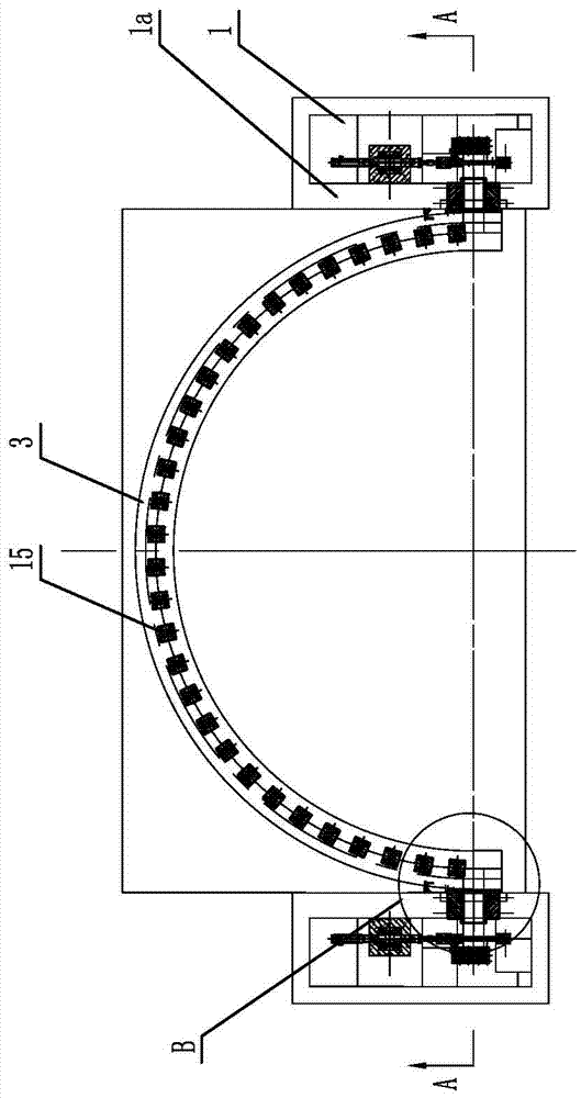
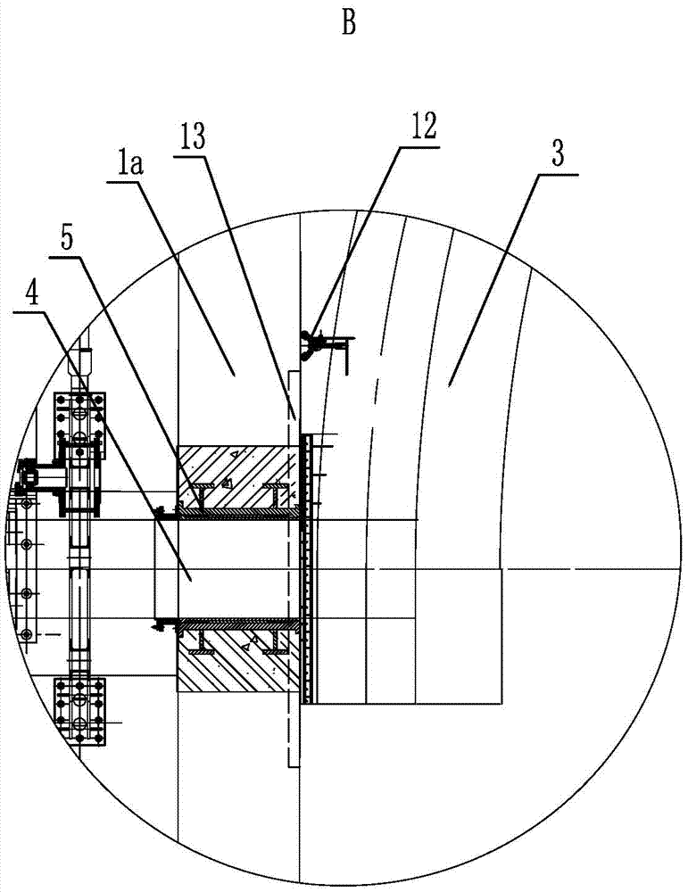
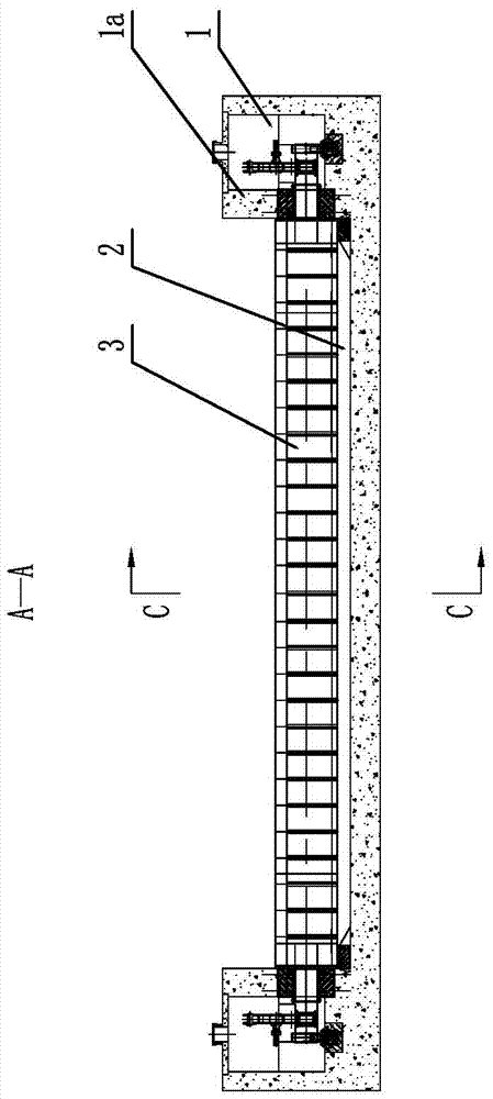
[0029] like Figure 1-12, is a rainbow gate, including power chambers 1 arranged on both sides of the river, a sill 2 at the bottom of the river is arranged between the power chambers 1 on both sides, and a gate is arranged between the power chamber walls 1a on both sides, The door body of the gate is arched, and the left and right sides of the door body are all provided with a rotating shaft 4 near the position of the power chamber wall 1a, and a shaft sleeve 5 matching the rotating shaft 4 is embedded in the power chamber wall 1a, and the rotation The shaft 4 extends into the power chamber 1 after passing through the corresponding bushing 5, and the power chamber 1 is provided with a driving device that can drive the rotating shaft 4 to rotate; the arched gate 3 is set corresponding to the bottom sill 2, and the arched gate 3 is closed , the bottom of the arch gate 3 is in contact with the sill 2. The rotating shaft 4 is arranged at the middle position of the height of the ...


PUM


Abstract

The invention discloses a rainbow-shaped gate and belongs to the field of water conservancy machinery. The rainbow-shaped gate comprises power chambers arranged on two sides of a riverway, a bottom sill located at the bottom of the riverway is arranged between the power chambers on the two sides, and a gate body is arranged between power chamber wall bodies on the two sides; the gate body of the gate is in an arch shape, the left side and the right side, close to the power chamber wall bodies, of the gate body are both provided with rotating shafts, shaft sleeves matched with the rotating shafts are embedded in the power chamber wall bodies, the rotating shafts penetrate through the corresponding shaft sleeves and then stretch into the power chambers, and the power chambers are internally provided with drive devices capable of driving the rotating shafts to rotate; and the arch-shaped gate body corresponds to the bottom sill, and when the gate body is closed, the bottom of the arch-shaped gate body is in contact with the bottom sill. By means of the rainbow-shaped gate, water retaining and water drainage can be performed normally, strength of the steel gate is improved, and deformation, caused by river water impact, of the steel gate is avoided; and the cost is lowered, the original natural state of a river is maintained, and trafficability is better.

Description

technical field [0001] The invention belongs to the field of water conservancy machinery, in particular to a water conservancy gate. Background technique [0002] In the prior art, there is a steel dam gate, its patent application number: 2007100242956; application date: 2007.07.28; its structure includes a steel beam frame, a door leaf welded and wrapped with steel plates outside the steel beam frame, and two sides of the door leaf Seal, the bottom edge of the door leaf is rigidly connected to the bottom shaft, and the two ends of the bottom shaft have inherent transmission parts. Weld some reinforcing ribs. When the gate is working, the gear or fan gear rotates, thereby driving the bottom shaft to rotate. When the gate leaf is upright, it will store water, and when the gate leaf is lying down, it will flood. The surface of the gate is constantly impacted by the river water. If the width of the river channel is wide, stress concentration will be formed in the middle of th...

Claims


Application Information

Patent Timeline
Patent Type & Authority Applications(China)
IPC IPC(8): E02B7/40
CPCE02B7/40
Inventor 陈文珠
Owner YANGZHOU CHUMEN ELECTROMECHANICAL DEVICES MFG
Why Eureka
Try Eureka