A converter and its modulation method
A converter and switching device technology, applied in the direction of converting DC power input to DC power output, instruments, converting AC power input to DC power output, etc., can solve the high frequency leakage current control scheme, large loss of components and conversion efficiency Low problems, to avoid common mode interference, reduce losses, and take up less space
- Summary
- Abstract
- Description
- Claims
- Application Information
AI Technical Summary
Problems solved by technology
Method used
Image


Examples
Embodiment 1
[0060] Such as figure 1 As shown, a converter of this embodiment includes a power switch tube S 1 , S 2 , S 3 , S 4 and S 5 , inductance L in and capacitance C 1 , also includes a diode D; one end of the DC side of the converter is connected to the inductor L in connected at one end, the inductance L in The other end of the power switch tube S 1 The terminal 1 of the diode D is connected to the anode of the diode D, and the cathode of the diode D is respectively connected to the power switch tube S 2 and S 4 terminal 1 and capacitor C 1 One end of the capacitor C 1 The other ends are connected to the power switch tube S 3 and S 5 Terminal 2, the other end of the DC side of the converter, the power switch tube S 1 and S 2 Terminal 2, power switch tube S 3 Terminal 1 and one end of the AC side of the converter are both grounded; the power switch tube S 5 Terminal 1 and power switch tube S 4 Terminal 2 is connected to the other end of the AC side of the converte...
Embodiment 2
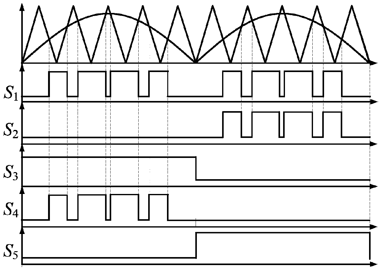
[0066] According to the converter described in Embodiment 1, this embodiment proposes a modulation method for the converter, such as figure 2As shown, the modulation wave is the absolute value of the sine wave, compared with the triangular wave carrier to obtain the SPWM wave, as the power switch tube S 1 switching signal; in the entire power frequency cycle, the power switch tube S 1 Always work in the SPWM state; in the positive half cycle of the power frequency, the power switch tube S 1 with S 4 synchronous, the power switch tube S 3 In the conduction state, the power switch S 2 and S 5 In the off state; in the negative half cycle of the power frequency, the power switch tube S 3 and S 4 are in the off state, the power switch tube S 5 In the open state, the power switch tube S 2 with S 1 The working status is the same.
[0067] 2.1 Analysis of working principle
[0068] 2.1.1 Analysis of working principle in DCM state
[0069] Table 1 is image 3 The switchin...
Embodiment 3
[0129] A converter of this embodiment has basically the same effect as that of Embodiment 1, such as Figure 20 shown, including the power switch S 1 , S 2 , S 3 , S 4 , S 5 and S 6 , inductance L in and capacitance C 1 ; One end of the DC side and the inductance L in connected at one end, the inductance L in The other end of the power switch tube S 1 terminal 1 and the power switch S 6 Terminal 1 is connected, the power switch tube S 6 Terminal 2 is respectively connected to the power switch tube S 2 and S 4 terminal 1, and capacitor C 1 One end of the capacitor C 1 The other ends are connected to the power switch tube S 3 and S 5 Terminal 2; the other end of the DC side, the power switch tube S 1 and S 2 Terminal 2, power switch tube S 3 Terminal 1 and one end of the AC side are grounded; the power switch tube S 5 Terminal 1 and power switch tube S 4 Terminal 2 is connected to the other end of the AC side; among them, the power switch tube S 2 , S 3 , ...
PUM
 Abstract
Description
Claims
Application Information
 - R&D
- Intellectual Property
- Life Sciences
- Materials
- Tech Scout
- Unparalleled Data Quality
- Higher Quality Content
- 60% Fewer Hallucinations
Browse by: Latest US Patents, China's latest patents, Technical Efficacy Thesaurus, Application Domain, Technology Topic, Popular Technical Reports.
© 2025 PatSnap. All rights reserved.Legal|Privacy policy|Modern Slavery Act Transparency Statement|Sitemap|About US| Contact US: help@patsnap.com