Novel methanol reformer
A reformer, methanol technology, applied in electrochemical generators, chemical instruments and methods, fuel cells, etc., can solve the problems of small contact area between methanol and water vapor and catalyst, and insufficient mixing of reactants, etc. Reforming efficiency and heat exchange efficiency, compactness and high-efficiency vibration resistance, the effect of improving hydrogen production
- Summary
- Abstract
- Description
- Claims
- Application Information
AI Technical Summary
Problems solved by technology
Method used
Image
Examples
Embodiment 1
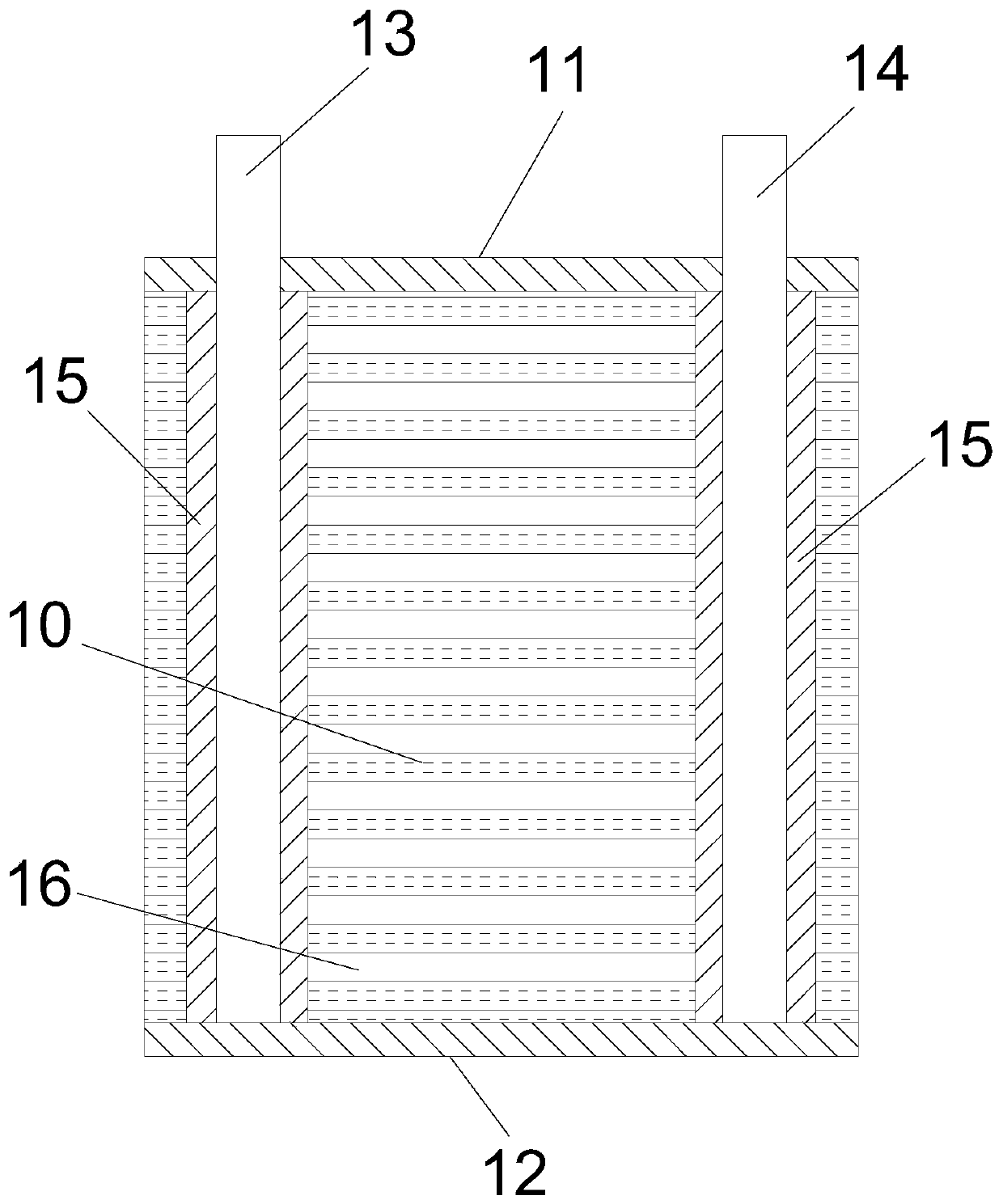
[0032] Such as figure 1 As shown, the present invention provides a novel methanol reformer, comprising a diversion mixing plate 10 and a catalyst coating, the diversion mixing plate 10 is a honeycomb structure throughout, the diversion mixing plate 10 is an aluminum alloy material, and the diversion mixing plate 10 Both the inner and outer side walls are provided with a catalyst coating. The catalyst coating can be a HTCB-7 methanol reforming hydrogen production catalyst. The methanol reforming reaction is an endothermic reaction. The heat exchange area is increased by the diversion mixing plate 10, which can Heating is carried out by a heating medium, the heating medium is a heater, and the flameless catalytic combustion catalyst can also be coated on the diversion mixing plate for direct heating by catalytic combustion. The flameless catalytic combustion catalyst is a metal or a metal oxide, specifically copper, chromium , nickel, vanadium, manganese, iron, cobalt and other ...
Embodiment 2
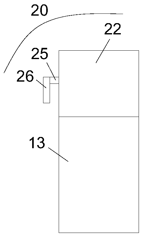
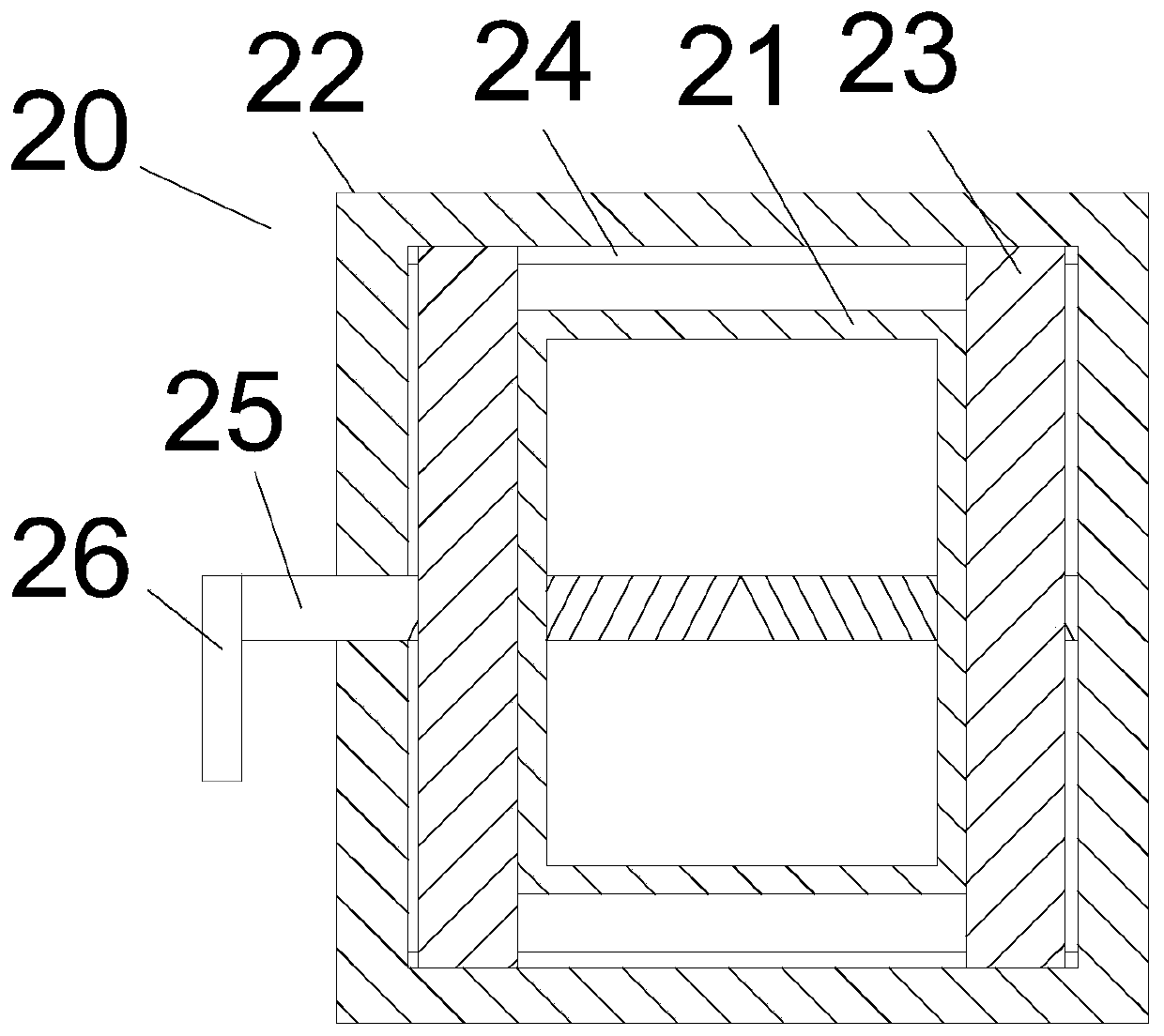
[0043] Such as figure 2 , 3 , 4, in order to be able to regulate the fluid flow, the preferred technical solution is that a flow regulating device 20 is arranged on the liquid inlet pipe 13, and the flow regulating device 20 includes a regulating pipe 21, a regulating ring 22 and a regulating block 23, and the regulating pipe 21 is arranged on In the adjustment ring 22, one port of the adjustment ring 22 is fixedly connected with the liquid inlet pipe 13, and the adjustment pipe 21 communicates with the liquid inlet pipe 13. The two opposite sides of the adjustment ring 22 are provided with slideways 24, and the slideway 24 enters the liquid vertically. The tube 13 is set, and the two ends of the slideway 24 can be slidably provided with an adjustment block 23, the adjustment block 23 is connected with the outer wall of the adjustment tube 21, the adjustment tube 21 is located between the two adjustment blocks 23, and the adjustment block 23 and the adjustment tube 21 are ins...
Embodiment 3
[0048] Such as Figure 5 , 6 , 7, in order to slow the flow of the fluid flowing out of the regulating pipe 21, the preferred technical solution is that a stopper 29 and a rotating rod 30 are arranged in the regulating pipe 21, the rotating rod 30 is arranged in parallel with the lead screw 25, and the rotating rod 30 It is rotatably connected with the inner wall of the regulating tube 21, and the torsion spring 31 is connected between the rotating rod 30 and the inner wall of the regulating pipe 21. The stopper 29 is located between the screw 25 and the rotating rod 30, and the stopper 29 and the leading screw 25 pass through the first The rope 32 is connected, and the block 29 is connected with the rotating rod 30 through a second rope 33 .
[0049] In order to make the fluid flowing out of the regulating tube 21 mix more completely, the preferred technical solution is that the stopper 29 is provided with a spoiler groove 34 towards the lead screw 25 side, and the notch of ...
PUM
 Abstract
Description
Claims
Application Information
 - R&D
- Intellectual Property
- Life Sciences
- Materials
- Tech Scout
- Unparalleled Data Quality
- Higher Quality Content
- 60% Fewer Hallucinations
Browse by: Latest US Patents, China's latest patents, Technical Efficacy Thesaurus, Application Domain, Technology Topic, Popular Technical Reports.
© 2025 PatSnap. All rights reserved.Legal|Privacy policy|Modern Slavery Act Transparency Statement|Sitemap|About US| Contact US: help@patsnap.com


