Vehicle lamp light source device and vehicle lamp module

A light source and vehicle lamp technology, which is applied in the automotive field, can solve the problems of reducing the visible distance of road signs, weakening, and reducing driving safety, etc., and achieves the effects of improving the visible distance, high safety factor, and reducing heat generation.

Pending Publication Date: 2019-06-18
索罗紫光(上海)科技有限公司
View PDF0 Cites 3 Cited by
  • Summary
  • Abstract
  • Description
  • Claims
  • Application Information

AI Technical Summary

Problems solved by technology

[0008] 1) The lack of near-ultraviolet bands leads to the lack of ultraviolet light excitation for road signs containing fluorescent media (the excited wavelength of the fluorescent media is <400nm), which reduces the extra brightness of the fluorescent media by nearly twice, reducing the nighttime road traffic. The clarity of the signboard being seen by the driver reduces the visual distance of the road signboard and reduces driving safety
[0009] 2) At the same time, due to the lack of power distribution of multi-segment light waves, such as cyan and red, the color reproduction of the illuminated object is inferior, which weakens the driver's correct judgment of pedestrians, terrain, and objects on the road
[0010] 3. In addition, the life of the current car lights is greatly affected by heat. How to quickly diffuse the heat of the illuminant wafer of the light source is also a problem that needs to be considered

Method used


Image

  • Vehicle lamp light source device and vehicle lamp module
  • Vehicle lamp light source device and vehicle lamp module
  • Vehicle lamp light source device and vehicle lamp module

Examples


Embodiment 1

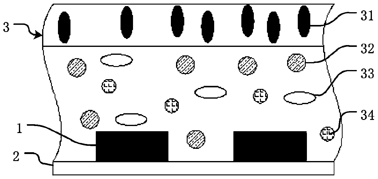
[0082] The light source adopts a formally installed NUV crystal element 1 and is placed in the PLCC / ceramic multi-bowl holder 2. The NUV crystal element 1 is fixed on the positive and negative electrodes at the bottom of the PLCC / ceramic multi-bowl holder 2 through crystal bonding glue, and is respectively connected by metal wires 11. Connect the positive and negative terminals 21 of the NUV crystal unit 1 and the internal electrode of the PLCC / ceramic multi-bowl cup holder 2, the phosphor silica gel layer 3 is filled with the PLCC / ceramic multi-bowl cup holder 2, and the layering methods of phosphors of different colors are set as described above . Its installation structure is as Figure 8 , Figure 11 shown.

Embodiment 2

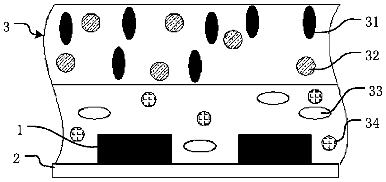
[0084] The light source is placed in the PLCC / ceramic multi-bowl cup holder 2 by flip-chip NUV crystal unit 1, and the NUV crystal unit 1 is connected to the internal positive and negative electrodes 21 of the electrodes of the PLCC / ceramic multi-bowl cup holder 2 through soldering tin, and the phosphor powder silica gel layer 3 is filled The PLCC / ceramic multi-bowl support 2 is filled, and a white glue reflective layer (optional) 8 is coated between the fluorescent powder silica gel layer 3 and the bottom of the PLCC / ceramic multi-bowl support 2 . Its installation structure is as Figure 9 , Figure 12 shown.

Embodiment 3

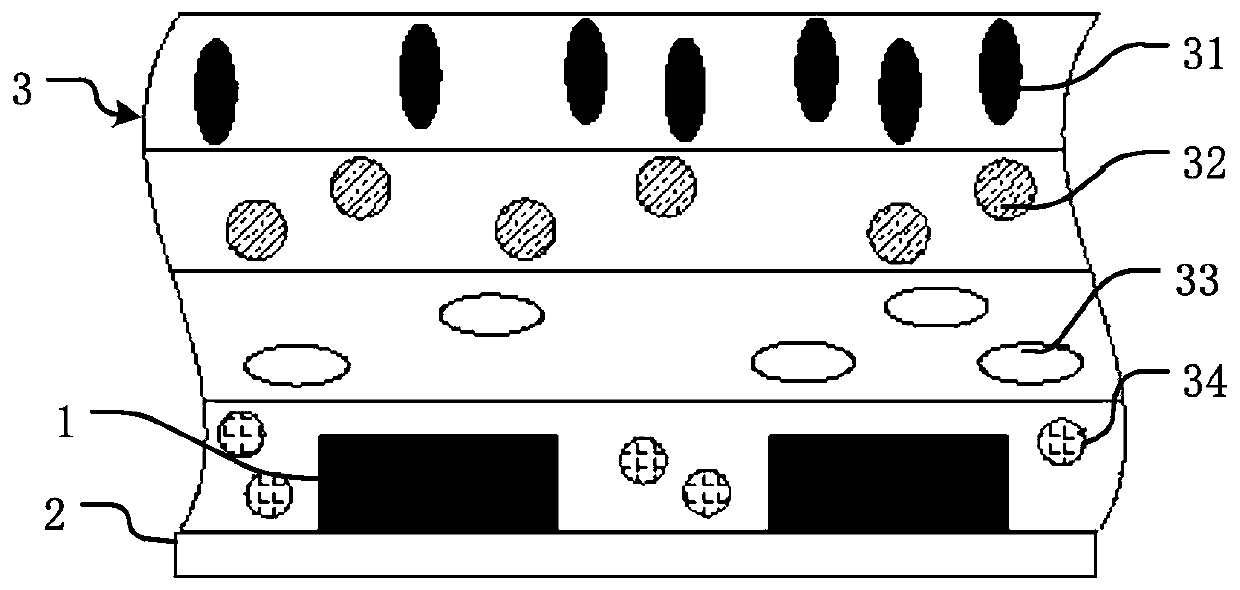
[0086] The light source is placed in the PLCC / ceramic multi-bowl holder 2 by flip-chip NUV crystal unit 1, and the NUV wafer 1 is respectively connected to the internal positive and negative electrodes 21 of the electrodes of the PLCC / ceramic multi-bowl holder 2 through the solder cap 121 of the copper pillar 12, Phosphor powder silica gel layer 3 is filled with PLCC / ceramic multi-bowl cup support 2, and the metal surface at the bottom of PLCC / ceramic multi-bowl cup support 2 is plated with a highly reflective metal coating, such as a silver layer, or in phosphor silica gel layer 3 and PLCC / A white glue reflective layer is coated between the bottoms of the multi-bowl support 2 of the ceramics. Its installation structure is as Figure 10 , Figure 13 shown.


PUM


Abstract

The invention provides a vehicle lamp light source device and a vehicle lamp module. The vehicle lamp light source device comprises one or a plurality of light-emitting wafers and a base for mountingthe wafers; the wafers are packaged on the base by a fluorescent powder silica gel layer; the wafers are NUV (Near Ultraviolet) gallium nitride LED (Light-Emitting Diode) wafers with a light-emittingwavelength range of 380nm to 420nm, and light finally output to the outside is near natural light; the base is a substrate of a PLCC / ceramic bracket or COB integrated light source; and the wafers forma single connection, parallel connection, serial connection or series-parallel connection mounting mode on the base. According to the invention, by using NUV gallium nitride LEDs as light sources, problems of NUV loss and color distortion which are caused by adoption of an LED blue light wafer in the prior art are solved; and by a proportion of the fluorescent powder silica gel layer, the light finally output to the outside becomes the near natural light similar with the sunlight, so that the field of vision of a driver is greatly changed, and a safe viewing distance is improved. Moreover, the near natural light does not contain strong blue white light which can instantaneously make people blind, and thus, the vehicle lamp light source device has a higher safety coefficient than a HID (High intensity Discharge) head lamp.

Description

technical field [0001] The invention relates to the field of automobiles, in particular to a car light source device capable of improving ultraviolet light excitation and enhancing color reproduction, and a car light module using the car light source device. Background technique [0002] The current light source of headlights mainly adopts white light source of halogen lamp, xenon lamp, laser lamp or LED blue light (420nm-470nm) wafer. [0003] Halogen lamp is an improved version of ordinary incandescent lamp. Its bulb cavity is filled with halogen gas such as iodine and bromine, which replaces the vacuum of incandescent lamp. Black, so that the filament can withstand higher temperature and produce more light. However, the light of the halogen lamp is yellowish, the brightness is low, the power consumption is large, the irradiation distance is limited, and the mold of the lamp is large, and the service life is only a few hundred hours. [0004] Xenon lamp (HID): It is a ki...

Claims


Application Information

Patent Timeline
Patent Type & Authority Applications(China)
IPC IPC(8): H01L33/50H01L33/64H01L25/075F21S41/141F21S45/48F21W107/10F21Y115/10
Inventor 杨人毅曾光明李名信
Owner 索罗紫光(上海)科技有限公司
Why Eureka
Try Eureka