Chamfering blade and cutter rod special for bearing
A blade and chamfering technology, applied to lathe tools, accessories of tool holders, turning equipment, etc., can solve problems such as scratching blades, easy to block wires, and damaged products, so as to improve efficiency, ensure quality, The effect of improving the service life
- Summary
- Abstract
- Description
- Claims
- Application Information
AI Technical Summary
Problems solved by technology
Method used
Image
Examples
Embodiment 1
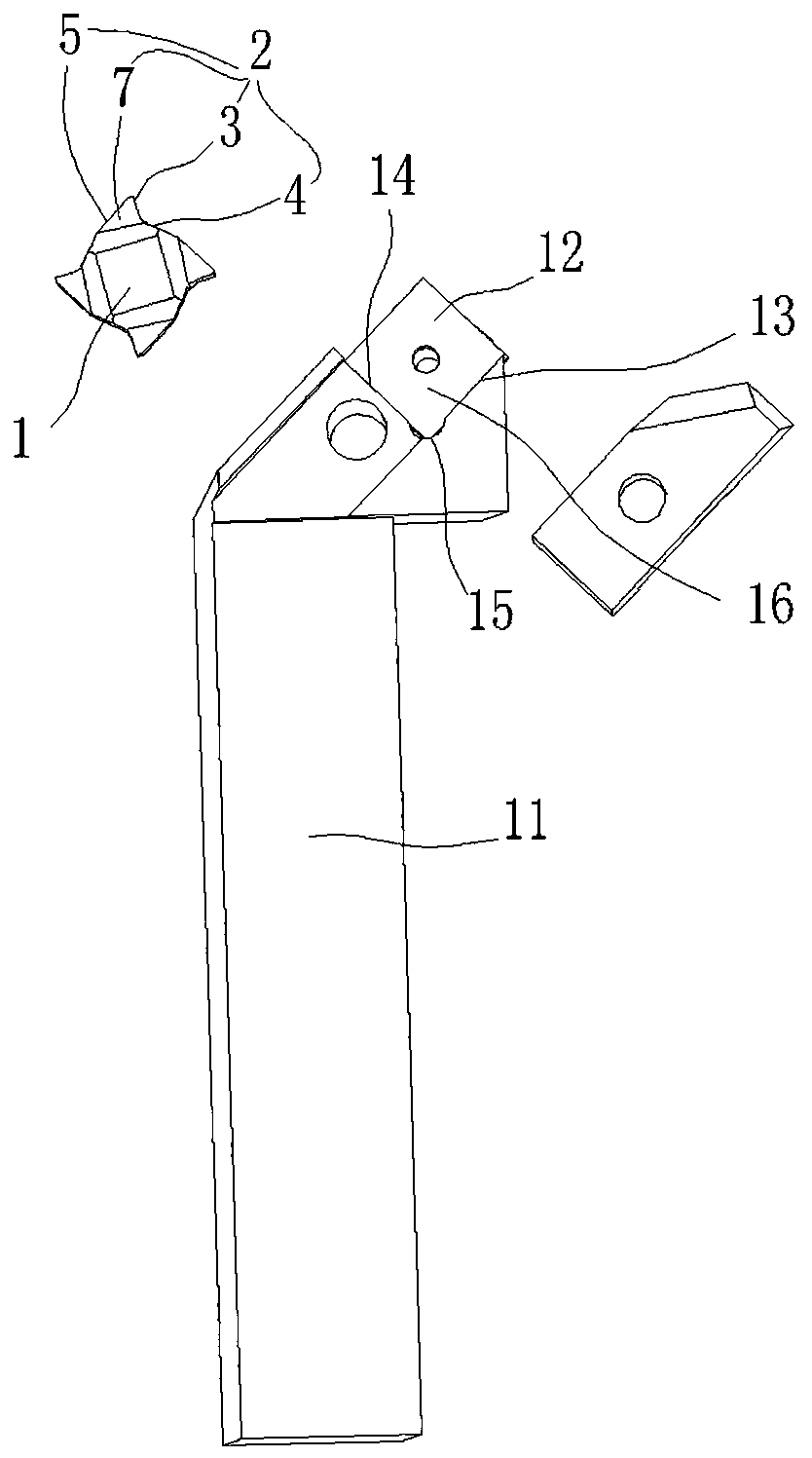
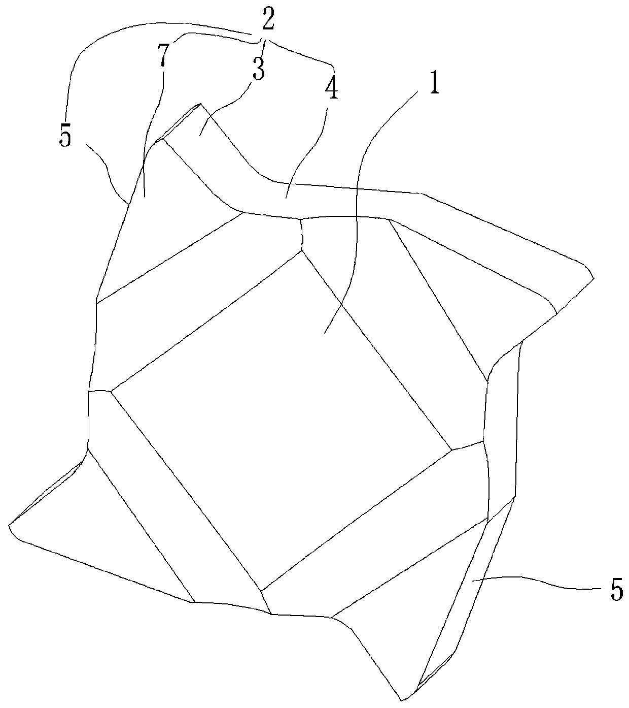
[0025] In this embodiment, the blade body 1 is provided with three cutting parts 2 . Through the three cutting parts 2, the overall shape of the insert body 1 is triangular, which has better stability and prevents vibration of the bearing during chamfering.
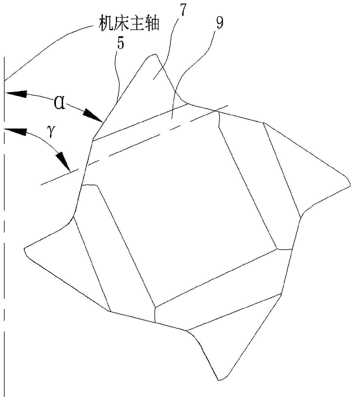
[0026] In this embodiment, the rotation angle α is 45 degrees. This rotation angle α degrees results in a chip removal surface with a larger space on the insert body 1 .
[0027] In this embodiment, the first inclination angle β is 6 degrees. Through the first inclination angle β, the iron wire is discharged relatively slowly and orderly, and it is discharged in a slide type, preventing the blade from being too large as a whole, and the blade is too small and has no cutting strength and is easy to collapse, or is too small Or when it is at a negative angle, the iron wire cannot be discharged from the chip removal surface.
[0028] In this embodiment, the second inclination angle γ is 80 degrees. Through the second inc...
Embodiment 2
[0034] In this embodiment, the blade body 1 is provided with three cutting parts 2 . Through the three cutting parts 2, the overall shape of the insert body 1 is triangular, which has better stability and prevents vibration of the bearing during chamfering.
[0035] In this embodiment, the rotation angle α is 65 degrees. This angle of rotation α degrees results in a relatively small-space chip removal surface 7 on the insert body 1 .
[0036] In this embodiment, the first inclination angle β is 8 degrees. Through the first inclination angle β, the iron wire is discharged relatively quickly, and it is discharged in a slide type, preventing the blade from being too large inclination and too small in size without cutting strength and easy to collapse, or too small, When it is at a negative angle, the iron wire cannot be discharged from the chip removal surface 7 .
[0037] In this embodiment, the second inclination angle γ is 95 degrees. Because the wire discharge area is sma...
Embodiment 3
[0043] In this embodiment, four cutting parts 2 are provided on the blade main body 1 . While considering the cutting strength and stability, it ensures the effective use of the blade and saves costs. Through a large number of tests, four cutting parts 2 are selected on the blade main body 1 .
[0044] In this embodiment, the rotation angle α is 45 degrees. This rotation angle α degrees results in a chip removal surface with a larger space on the insert body 1 .
[0045] In this embodiment, the first inclination angle β is 6 degrees. Through the first inclination angle β, the iron wire is discharged relatively slowly and orderly, and it is discharged in a slide type, preventing the blade from being too large as a whole, and the blade is too small and has no cutting strength and is easy to collapse, or is too small Or when it is at a negative angle, the iron wire cannot be discharged from the chip removal surface.
[0046] In this embodiment, the second inclination angle γ ...
PUM
 Abstract
Description
Claims
Application Information
 - R&D
- Intellectual Property
- Life Sciences
- Materials
- Tech Scout
- Unparalleled Data Quality
- Higher Quality Content
- 60% Fewer Hallucinations
Browse by: Latest US Patents, China's latest patents, Technical Efficacy Thesaurus, Application Domain, Technology Topic, Popular Technical Reports.
© 2025 PatSnap. All rights reserved.Legal|Privacy policy|Modern Slavery Act Transparency Statement|Sitemap|About US| Contact US: help@patsnap.com


