
Antenna helicoid partition limiting and data transmission integrating device

A helical surface and position-limiting technology, which can be applied to antennas, electrical components, etc., can solve the problems of high signal frequency, large size, and complex size of the device, and achieve the effect of accurate and stable transmission, compact design mechanism and small volume.

Inactive Publication Date: 2016-02-24
CHENGDU JINJIANG ELECTRONICS SYST ENG
View PDF5 Cites 4 Cited by
  • Summary
  • Abstract
  • Description
  • Claims
  • Application Information

AI Technical Summary

Problems solved by technology

[0002] In radar work, azimuth scanning usually requires the antenna azimuth to move continuously in the same direction over 360°, so mechanisms such as slip rings and speed-increasing gears are often used to form azimuth limit and data feedback devices, but in remote sensing and telemetry antennas and In medium and high-orbit satellite tracking antennas, the azimuth scanning angle is usually within ±360°. In order to ensure the tracking speed of the antenna and the azimuth movement of the antenna are continuous and effective, and various signal and control cables are not entangled, it is usually required that the azimuth of this type of antenna be continuous The movement is within 360°. At this time, the azimuth limit and data feedback are affected by continuous movement and various installation device limits and the volume of feedback components. It is impossible to arrange various components in a plane, so Slip rings are required, but because the signal frequency is too high, the manufacturing cost is too high, and there is also the problem of emission from the position of the limiting device
In order to solve such problems, usually such devices are not only complex and bulky, but also have low partition and limit accuracy, and the upper limit and data feedback devices cannot be integrated

Method used


Image

  • Antenna helicoid partition limiting and data transmission integrating device
  • Antenna helicoid partition limiting and data transmission integrating device
  • Antenna helicoid partition limiting and data transmission integrating device

Examples


Embodiment Construction

[0027] The present invention will be further described below in conjunction with accompanying drawing, protection scope of the present invention is not limited to the following:

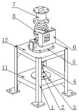
[0028] Such as figure 1 As shown in the figure, an antenna helical surface partition limit and data transmission integrated device includes a mounting frame 1, a dual-channel resolver transmitter 2, a coupling A3, a transmission shaft 4, a seat frame 5, a sliding seat 6, and a spiral sleeve 8 and shaft coupling B7. In this embodiment, the shaft coupling A3 is an elastic shaft coupling, and the shaft coupling B7 is an elastic shaft coupling. The installation frame 1 is provided with an installation layer A11 and an installation layer B12. The channel resolver transmitter 2 is installed in the installation layer A11, the seat frame 5 is installed on the upper surface of the installation layer B12, the transmission shaft 4 passes through the seat frame 5 and the installation layer B12, and one end of th...


PUM


Abstract

The invention discloses an antenna helicoid partition limiting and data transmission integrating device, comprising a mounting rack (1), a double-channel rotary transmitter (2), a coupling A (3), a transmission shaft (4), a seat frame (5), a sliding seat (6), a helical casing (8) and a coupling B (7), wherein the mounting rack (1) is provided with a mounting layer A (11) and a mounting layer B (12), the double-channel rotary transmitter (2) is mounted in the mounting layer A (11), the seat frame (5) is mounted on the upper surface of the mounting layer B (12), the transmission shaft (4) penetrates through the seat frame (5) and the mounting layer B (12), one end of the transmission shaft (4) is connected with the double-channel rotary transmitter (2) through the coupling A (3), the helical casing (8) is arranged above the seat frame (5), the other end of the transmission shaft (4) is mounted in the helical casing (8), and the sliding seat (6) is mounted on the seat frame (5). The device has the advantages of high partition limiting precision, small size and the like.

Description

technical field [0001] The invention relates to antenna angle detection, in particular to an integrated device for antenna helicoid partition limit and data transmission, which can continuously detect antenna angle and monitor automatic electromechanical limit. Background technique [0002] In radar work, azimuth scanning usually requires the antenna azimuth to move continuously in the same direction over 360°, so mechanisms such as slip rings and speed-increasing gears are often used to form azimuth limit and data feedback devices, but in remote sensing and telemetry antennas and In medium and high-orbit satellite tracking antennas, the azimuth scanning angle is usually within ±360°. In order to ensure the tracking speed of the antenna and the azimuth movement of the antenna are continuous and effective, and various signal and control cables are not entangled, it is usually required that the azimuth of this type of antenna be continuous The movement is within 360°. At this ...

Claims


Application Information

Patent Timeline
IPC IPC(8): H01Q3/06
CPCH01Q3/06
Inventor 蔡云林鹏杨雪峰母俊宏
Owner CHENGDU JINJIANG ELECTRONICS SYST ENG
Learn More