
Bile reinfusion type double-cavity T-shaped tube

A bile and lumen technology, applied in the field of disposable medical supplies, can solve the problems of secondary pollution components of bile, comfort of gastrointestinal mucosal skin mechanical stimulation, gastric mucosal damage, etc., to protect the intestinal mucosal barrier, effectively Helps bowel function and increases biliary pressure

Inactive Publication Date: 2019-06-18
何梅 +1
View PDF0 Cites 2 Cited by
  • Summary
  • Abstract
  • Description
  • Claims
  • Application Information

AI Technical Summary

Problems solved by technology

Recycle and store the bile before reinfusion. Recycling and storage will cause secondary pollution and damage to the components of the bile. If the storage time is too long, the bile may deteriorate.
Oral bile will cause damage to the gastric mucosa of the patient. The bile is extremely bitter, difficult to swallow and has an unpleasant taste. Oral bile will cause great psychological disturbance to the patient, and the bile acts on the small intestine and enters the stomach after oral administration. affect the efficacy of bile
The reinfusion of bile combined with enteral nutrition via nasoenteric tube or jejunostomy may cause mechanical irritation and comfort to the gastrointestinal mucosa and the skin around the stoma because the catheter remains in the body for a long time. In particular, the insertion of enterostomy tube requires surgical operation, which increases the patient's pain, risk of infection and economic burden

Method used


Image

  • Bile reinfusion type double-cavity T-shaped tube
  • Bile reinfusion type double-cavity T-shaped tube

Examples


Embodiment Construction

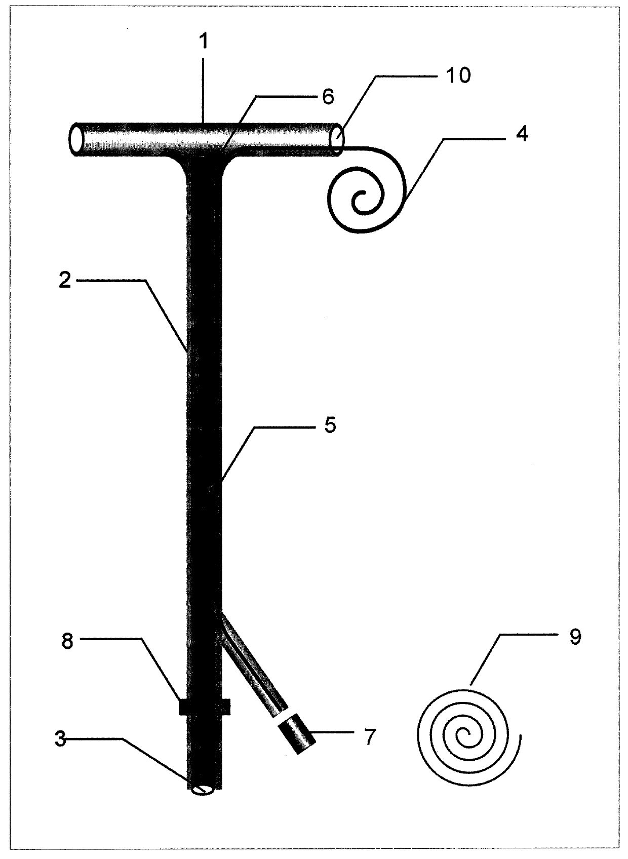
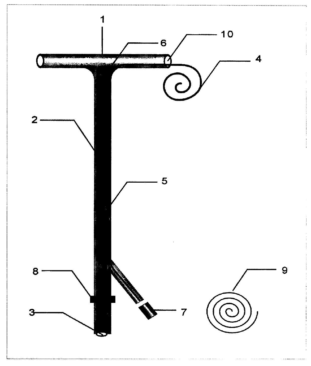
[0008] The embodiment of the invention is attached figure 1 Shown: figure 1 The vertical section of the main body of the double-lumen T-tube that can reinfuse bile in the middle is T-tube 2, one end of T-tube 2 is connected to the parallel segment T-arm 1, and the other end of T-tube 2 is connected to the common interface 3; a separate small lumen is attached to the T-tube 2 4. The outlet of the small lumen 4 is an interface 7 that can be connected to positive pressure. The large and small lumens are connected through the one-way valve 5, and the opening direction of the one-way valve is the small lumen; during surgery, the parallel section T of the double-lumen T-tube Arm 1 is placed in the patient's common bile duct, and the small lumen 4 is sent into the duodenum with the help of the guide wire 9 by Seidinger's technique for reinfusion of bile or nutrient solution. Connect positive pressure connector 7. The vertical T-tube 1 is fixed on the abdominal wall under the patien...


PUM


Abstract

The invention discloses a double-cavity T-shaped tube capable of recycling bile. The double-cavity T-shaped tube is characterized in that a vertical section of a double-cavity T-shaped tube main bodyis a T tube, and a parallel section of the double-cavity T-shaped tube main body is a T arm; the T tube is internally provided with a large tube cavity and a small tube cavity, and the larger tube cavity and a large tube cavity in the T arm mutually communicate and are both used for draining the bile; a free long separate pipeline penetrating out from an outlet in one side of the T arm section isformed on the T arm section by the small tube cavity and communicates with the small tube cavity in the T tube wall, and the free long separate pipeline and the small tube cavity are both bile reinfusion passages; a guide wire is assembled in the small tube cavity, and the small tube cavity can be sent into the duodenum through the guide wire; a one-way valve is arranged on the small tube cavity wall in the middle and lower section of the T tube and is open facing the small tube cavity, and when an outlet of the large tube cavity is clamped, the bile flows into the small tube cavity from the one-way valve, and enters the duodenum for bile reinfusion; and the other end of the T tube is connected with two outlets for bile drainage and reinfusion, and reinfusion pipeline flushing correspondingly. Smooth bile drainage after surgery can be guaranteed, the bile can also be effectively reinfused into an intestine, and thus the purpose of accelerating rehabilitation is achieved.

Description

Technical field [0001] The invention relates to a double-cavity T-shaped tube capable of reinfusing bile that needs to be used in the biliary tract exploration operation for patients in the medical field, and is a disposable medical product. Background technique [0002] Bile duct stones, biliary inflammation, and biliary obstruction caused by various reasons require biliary exploration and T-tube drainage. At present, the T-tubes used in major hospitals in China are made of latex. They are composed of two "arms" and a long drainage tube. (In the operation, the arm of the T-tube is placed in the patient's common bile duct, the T-tube drainage tube passes through the abdominal wall under the patient's right costal margin to the outside, and is sutured and fixed on the skin. Bile flows into the intestinal tract through one part of the T-arm and the other part into the T-tube. Tube to the drainage bag. The purpose of placing the T tube: 1 to drain bile, reduce the pressure of ...

Claims


Application Information

Patent Timeline
Patent Type & Authority Applications(China)
IPC IPC(8): A61M25/14
Inventor 何梅杨艳英杨静
Owner 何梅
Learn More