
Air Self-Breathing Membraneless Microfluidic Fuel Cell with Integral Cylindrical Anode

A fuel cell and self-breathing technology, applied in fuel cells, circuits, electrical components, etc., can solve problems such as large fuel evaporation chamber, short residence time, and limited reaction rate

Active Publication Date: 2020-10-30
CHONGQING UNIV
View PDF3 Cites 1 Cited by
  • Summary
  • Abstract
  • Description
  • Claims
  • Application Information

AI Technical Summary

Problems solved by technology

However, this solution will reduce the effective electrode area and reduce the battery output power
5) kjeang et al. (E.kjeang et.al., Electrochimica Acta, 2008) used a permeable porous anode to enhance fuel mass transfer in a convective manner. However, on the one hand, the hydraulic residence time of the fuel in the thin catalytic layer is short, and the reaction rate Limited; on the other hand, additional anode flow channels are required, which reduces volumetric energy or power density and is not conducive to system integration
6) Wang et al. (Y.Wang et.al., Applied Energy, 2015) used gaseous methanol vapor as fuel, but this solution requires a larger fuel evaporation chamber, which reduces volume energy or power density and is not conducive to system integration

Method used


Image

  • Air Self-Breathing Membraneless Microfluidic Fuel Cell with Integral Cylindrical Anode
  • Air Self-Breathing Membraneless Microfluidic Fuel Cell with Integral Cylindrical Anode
  • Air Self-Breathing Membraneless Microfluidic Fuel Cell with Integral Cylindrical Anode

Examples


Embodiment Construction

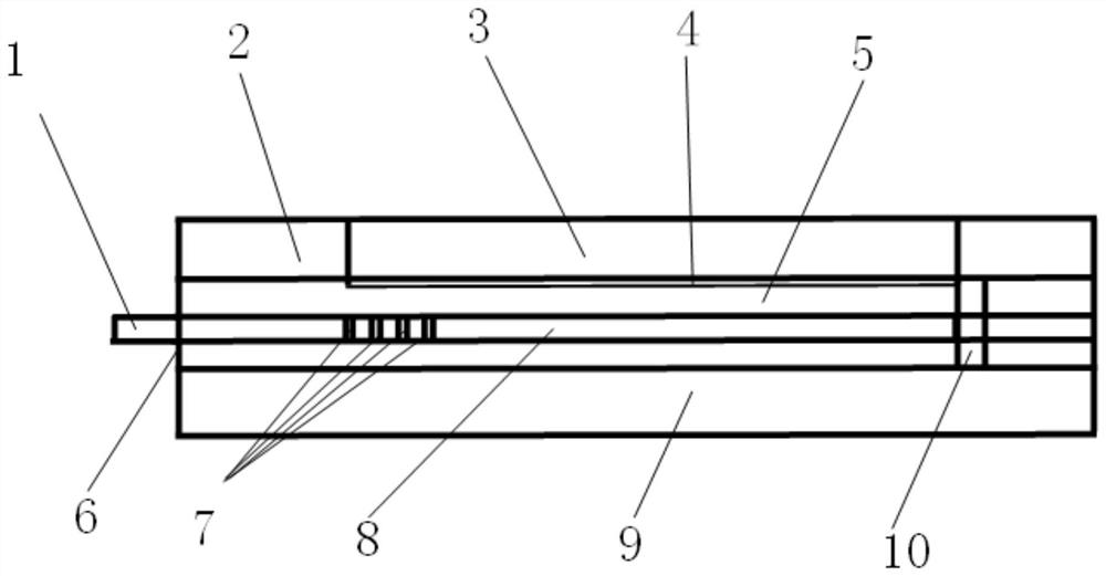
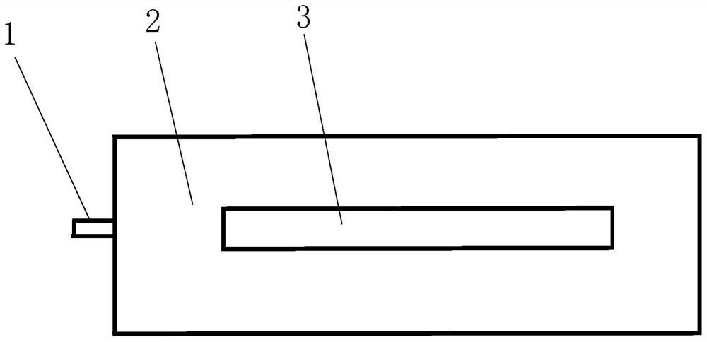
[0026] see Figure 1 to Figure 4, an air self-breathing membraneless microfluidic fuel cell with an integral cylindrical anode, comprising a membraneless microfluidic fuel cell main body, the membraneless microfluidic fuel cell main body comprising a cathode cover plate 2, an air self-breathing cathode 4, a flow Channel 5, cylindrical anode 8 and battery bottom plate 9, the cathode cover plate, flow channel and battery bottom plate 9 are all made of plastic; the cathode cover plate 2 is provided with a cathode air breathing hole 3, and the cathode air breathing hole 3 is arranged on Air is self-breathing above the cathode 4; the flow channel 5 is arranged between the cathode cover plate 2 and the battery bottom plate 9; the front end of the flow channel 5 is provided with an electrolyte inlet 6, and a metal round tube 1 is arranged in the flow channel 5; The outer surface of the metal round tube 1 is coated with a Pd / Nafion catalytic layer by repeated electrochemical depositio...


PUM


Abstract

The invention discloses an air-breathing membrane-free fluid fuel cell provided with an integrated cylindrical anode. The air-breathing membrane-free fluid fuel cell comprises a cathode cover plate, arunner and a cell base plate, a cathode air breathing hole is formed in the cathode cover plate, and an air-breathing cathode is arranged below the cathode air breathing hole. The air-breathing membrane-free fluid fuel cell is characterized in that the runner is arranged between the cathode cover plate and the cell base plate; a cylindrical metal tube is arranged in the runner; a catalyst layer is coated on the outer surface of the cylindrical metal tube; the cylindrical metal tube is arranged parallel to the air-breathing cathode; the front part of the cylindrical metal tube is a hollow tube, and the rest part is a solid tube; a plurality of overflow ports are formed in the tube wall at a junction of the hollow tube and the solid tube along the circumferential direction; a fuel inlet isformed in the front end of the cylindrical metal tube; a waste liquor outlet is formed in the cell base plate; and the waste liquor outlet is communicated with the runner. The air-breathing membrane-free fluid fuel cell disclosed by the invention can enhance fuel transmission, system integration is facilitated, and cell performance is improved; and the air-breathing membrane-free fluid fuel cell can be widely applied to the fields of energy sources, chemical industry and environmental protection.

Description

technical field [0001] The invention relates to the field of fuel cells, in particular to an air self-breathing membrane-free microfluidic fuel cell with an integral cylindrical anode. Background technique [0002] Lithium-ion batteries currently widely used have disadvantages such as low theoretical energy density, long charging time, and narrow normal use temperature range. Micro fuel cells often use methanol or formic acid with high energy density as fuel, which is significantly higher than the upper limit of theoretical energy density of lithium batteries; the operating environment is adaptable and the operating temperature range is wide; chemical energy is directly converted into electrical energy, and the theoretical energy conversion efficiency is high. ; The product has no pollution to the environment. Therefore, miniature fuel cells (such as miniature direct methanol or formic acid fuel cells) have unique advantages and broad application prospects in the new genera...

Claims


Application Information

Patent Timeline
Patent Type & Authority Patents(China)
IPC IPC(8): H01M8/0258H01M8/00H01M8/1009H01M8/1011
CPCY02E60/50
Inventor 朱恂周远张彪叶丁丁陈蓉廖强李俊付乾张亮
Owner CHONGQING UNIV
Learn More