


Quick Research
Generate reliable direction feasibility study reports for your R&D in just a few steps.

Technical Q&A
Discover and master advanced knowledge NOW. Basics, ideas, possibilities, all at once.

Find Solutions
As an expert in R&D theories, this can generate solutions to your technical problems instantly.

Evaluate Feasibility
Analyze your overall solution with one click, know your potential R&D risks in advance.

Monitor Landscape
Get weekly tech updates, stay abreast of the latest tech innovations and key insights.
Pressure bearing type plate heat exchanger
A plate heat exchanger, pressure-bearing technology, applied in the direction of heat exchanger shell, indirect heat exchanger, heat exchanger type, etc., can solve the problems of unsatisfactory pressure bearing effect and increase the pressure of heat exchange plate, so as to avoid The effect of bulging deformation, improving pressure resistance and reducing input cost
- Summary
- Abstract
- Description
- Claims
- Application Information
AI Technical Summary
Problems solved by technology
Method used
Image

Examples
Embodiment 1
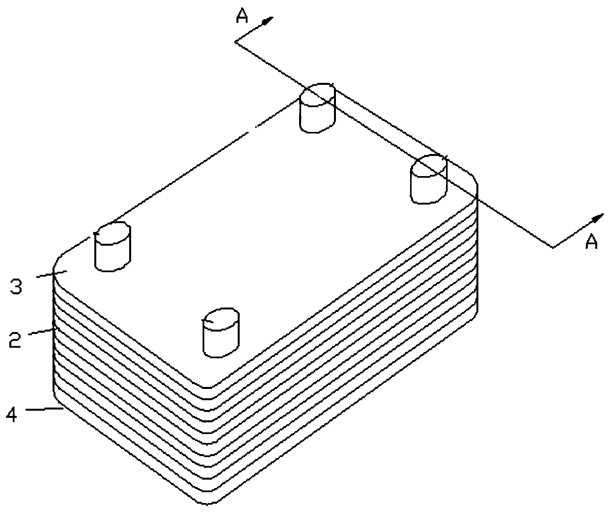
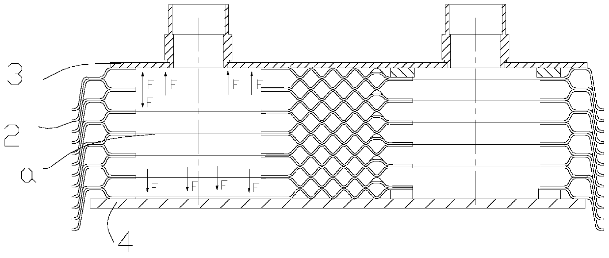
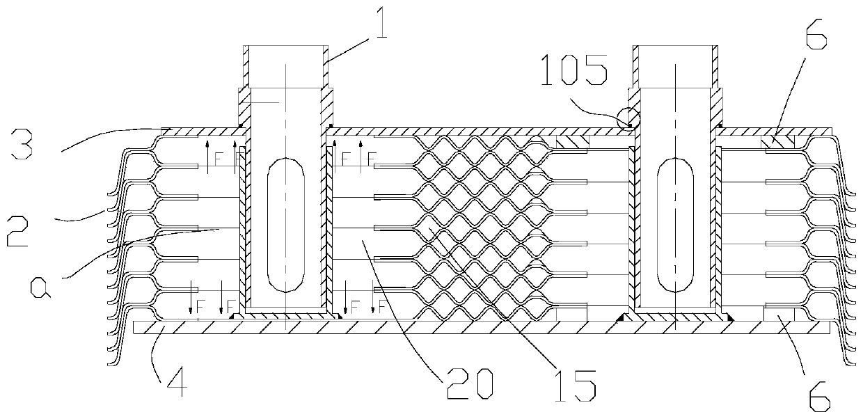
[0048] This embodiment relates to a pressure-bearing plate heat exchanger, which includes an upper end plate 3, a lower end plate 4, and a series of heat exchange plates 2 neatly laminated between the upper and lower end plates. The heat exchange channels 15 for the alternating flow of cold / heat medium, each heat exchange plate 2 is provided with four corner holes a, the same corner holes on a series of heat exchange plates are connected through, correspondingly forming a flow path for the flow of cold / heat medium or There are four fluid passages 20 flowing out, and the fluid passages 20 for the cold / heat medium are connected to the respective heat exchange flow passages 15 respectively. The upper end plate 3 is provided with an opening communicating with the fluid passages, and the connection device 1 is fixedly installed at the opening.
[0049] The connecting device 1 includes a connecting head 101 and a connecting seat 102 , a bottom plate 103 is fixed at the bottom of the ...
Embodiment 2
[0058] The structure of the heat exchanger in this embodiment is similar to the heat exchanger in Embodiment 1, the difference is that the nozzle socket of the nozzle device is different, and according to the laminated structure of the heat exchange plates of the plate heat exchanger, the upper and lower adjacent heat exchangers are used The in-out gap between the corner holes of the plate is used to fix the connecting pipe seat, and the welding operation is omitted. The specific difference is that the bottom of the socket 102 is a base plate 103, and the outer edge of the base plate is formed as a chuck 103'. The thickness of the outer edge is twice the corrugation depth of the heat exchange plate. In this way, the chuck 103' can It just snaps into the liquid inlet and outlet gap between the two lowermost corner holes a, and a gap b is opened on the chuck 103' so that the lowermost heat exchange channel can still communicate with the fluid channel.
[0059] The preparation me...
Embodiment 3
[0067] The structure of the heat exchanger in this embodiment is similar to the heat exchanger in Embodiment 1, the difference is that the nozzle sockets of the nozzle device are different, and according to the laminated structure of the heat exchange plates of the plate heat exchanger, the upper and lower adjacent heat exchangers are used The in-out gap between the corner holes of the plate is used to fix the connecting pipe seat, and the welding operation is omitted. The specific difference is that the bottom of the socket 102 is a bottom plate 103, and the outer edge of the bottom plate is formed as a chuck 103', and the thickness of the outer edge is twice the corrugation depth of the heat exchange plate. In this way, the chuck 103' can It just fits into the liquid inlet and outlet gap between the corner holes a of the two heat exchange plates corresponding to the lowermost heat exchange channel, and the chuck 103' has a gap b so that the lowermost heat exchange channel can...
PUM
 Abstract
Description
Claims
Application Information
 - R&D Engineer
- R&D Manager
- IP Professional
- Industry Leading Data Capabilities
- Powerful AI technology
- Patent DNA Extraction
Browse by: Latest US Patents, China's latest patents, Technical Efficacy Thesaurus, Application Domain, Technology Topic, Popular Technical Reports.
© 2024 PatSnap. All rights reserved.Legal|Privacy policy|Modern Slavery Act Transparency Statement|Sitemap|About US| Contact US: help@patsnap.com