
Lithium ion battery module management circuit

A lithium-ion battery and management circuit technology, applied in the field of lithium-ion battery module management circuits, can solve the problems of lack of module-level independent protection, no protection control function, battery pack safety problems, etc., to improve overall safety and reliability, Avoid overcharge and overdischarge, low cost effect

Pending Publication Date: 2019-05-21
福建飞毛腿动力科技有限公司
View PDF4 Cites 1 Cited by
  • Summary
  • Abstract
  • Description
  • Claims
  • Application Information

AI Technical Summary

Problems solved by technology

[0003] The module management circuits of the existing power battery packs and high-voltage energy storage battery packs do not have independent protection and control functions, but only have parameter detection and data communication functions. The communication method communicates with the external main control unit, transmits the battery module parameters to the main control unit, and then the main control unit controls the DC contactor of the main circuit to protect and control the entire battery pack. The entire lithium-ion battery management system has only one Level protection, lack of independent protection at the module level, when the protection control of the main circuit fails, the battery pack is prone to safety problems
Since this level of protection control needs to withstand high voltage and high current, DC contactors are commonly used as protection switches in the industry. In high-voltage and high-current applications, the connecting contacts of DC contactors are prone to adhesion and failure

Method used


Image

  • Lithium ion battery module management circuit
  • Lithium ion battery module management circuit

Examples


Embodiment Construction

[0019] The technical solution of the present invention will be specifically described below in conjunction with the accompanying drawings.

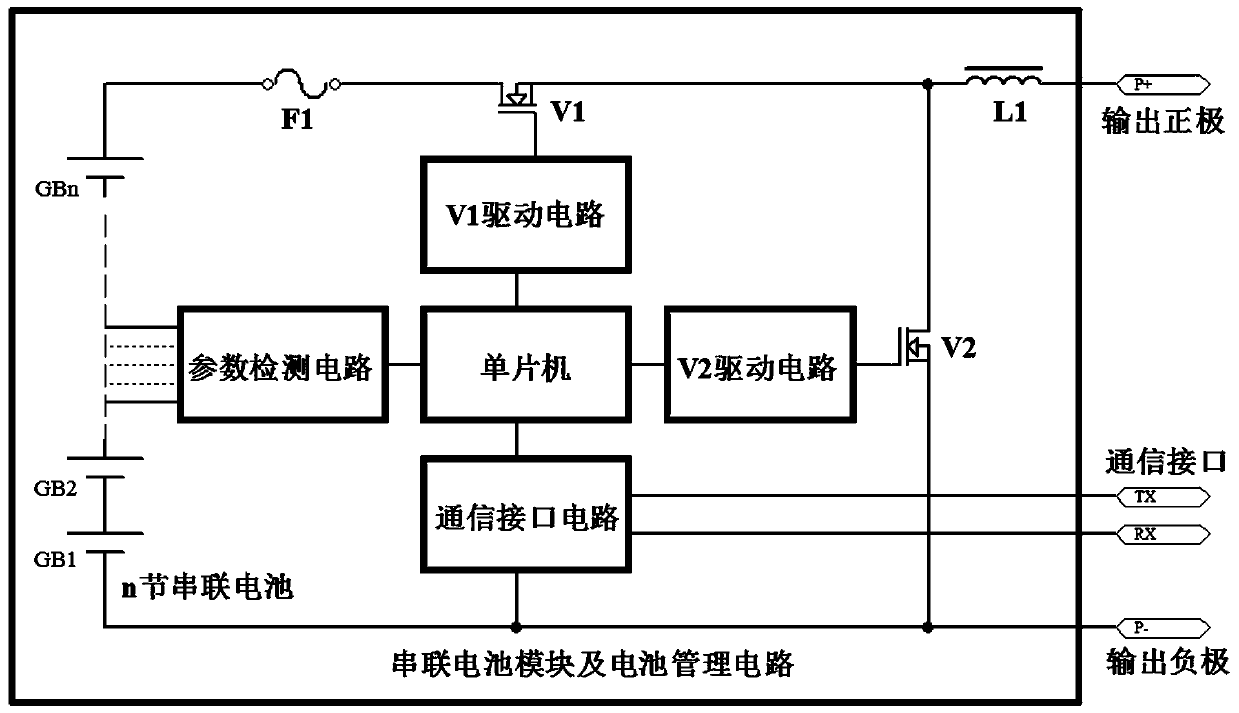
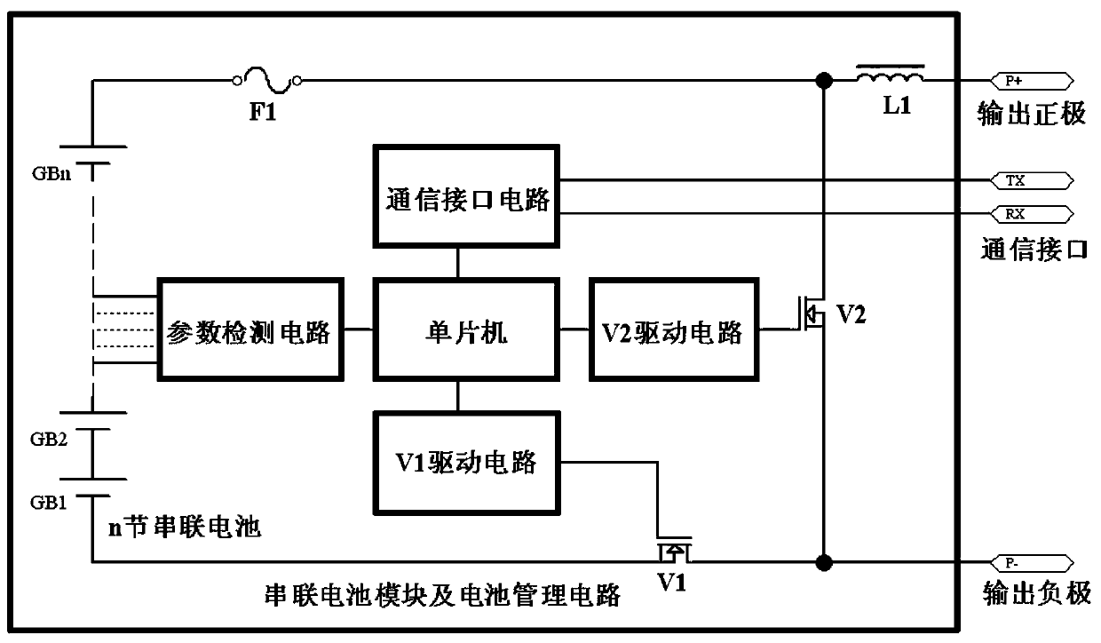
[0020] The purpose of the present invention is to add two field effect transistors to realize the independent protection function of the battery module in addition to the parameter detection circuit and communication function in the management circuit of the battery module, wherein one field effect transistor is connected in series with the battery, and the other field effect transistor Connected in parallel to the output terminal of the battery module, the single-chip microcomputer controls the on-off of the two field effect transistors respectively through the driving circuit. When the battery module is abnormal, the charging and discharging circuit of the battery module is cut off, and the output terminal is in a bypass conduction state. This not only ensures the safety of the battery module, but also does not affect the work of other n...


PUM


Abstract

The invention relates to a lithium ion battery module management circuit. The lithium ion battery module management circuit comprises a single chip, a parameter detection circuit, a first field-effecttube driving circuit, a second field-effect tube driving circuit, a first field-effect tube, a second field-effect tube, a fuse and a series battery module, wherein the parameter detection circuit, the first field-effect tube driving circuit and the second field-effect tube driving circuit are connected with the single chip. Besides battery module parameter detection and communication functions,the lithium ion battery module management module has another protection function independent of battery pack systems, so that battery modules can be independently protected, over-charging and over-discharging of the battery modules are avoided, and the battery modules are prevented from being charged and discharged at ultrahigh temperatures or ultralow temperatures; and the structure of the battery module management circuit can be realized by protection switches of the battery modules by adoption of field-effect tubes and the field-effect tubes only need to bear the voltage of the battery modules in specific application, so that low-cost field-effect tubes which resist low voltage and low-pass impedance can be selected, and then good economy and high cost performance are provided.

Description

technical field [0001] The invention belongs to the technical field of lithium-ion battery management systems, and in particular relates to a lithium-ion battery module management circuit. Background technique [0002] With the increasingly widespread application of lithium-ion batteries, more and more lithium-ion batteries are used in power batteries and energy storage systems. The lithium-ion battery packs used in electric vehicle power and large-scale energy storage in the industry are mostly used due to their high voltage. When it reaches 300V or even above 800V, the number of batteries in series is many, often reaching hundreds of strings. Therefore, the circuit structure of the battery pack is often designed in modules. Each module is 6 to 12 batteries in series, and the module will have a Battery management circuit, the function of the management circuit is mainly to monitor the parameters of the battery module and communicate with the external central control unit (a...

Claims


Application Information

Patent Timeline
IPC IPC(8): H02J7/00H02H7/18
Inventor 俞峰杨麒麟张许峰张凤敏
Owner 福建飞毛腿动力科技有限公司
Learn More