A leadless packaging structure and packaging method for a piezoresistive sensor

A technology of packaging structure and packaging method, which is applied to instruments, measuring devices, measuring fluid pressure, etc., can solve the adverse effects of sensor chip stability, response speed and natural frequency, thermal stress matching failure of packaging materials, and sensor chip natural frequency loss. and other problems, to achieve the effect of reducing thermal stress, good bonding strength and high reliability

Active Publication Date: 2021-03-23
XI AN JIAOTONG UNIV
View PDF5 Cites 0 Cited by
  • Summary
  • Abstract
  • Description
  • Claims
  • Application Information

AI Technical Summary

Problems solved by technology

[0003] The traditional wire lead packaging structure seals the front circuit of the sensor chip under the corrugated sheet filled with silicone oil, and the external pressure is indirectly transmitted to the pressure sensor chip through the corrugated sheet and the sealed silicone oil, resulting in the loss of the natural frequency of the sensor chip, which is not conducive to improving the performance of the sensor. responding speed
[0004] In addition, the traditional wire lead packaging structure will have problems such as thermal stress matching failure between packaging materials and thermal oxidation of packaging materials in high temperature environments, which will adversely affect the stability, response speed and natural frequency of the sensor chip.

Method used


Image

  • A leadless packaging structure and packaging method for a piezoresistive sensor
  • A leadless packaging structure and packaging method for a piezoresistive sensor
  • A leadless packaging structure and packaging method for a piezoresistive sensor

Examples


Embodiment Construction

[0046]The present invention will be described in further detail below in conjunction with the accompanying drawings and examples, which are used to explain the present invention, rather than limit the protection scope of the present invention.

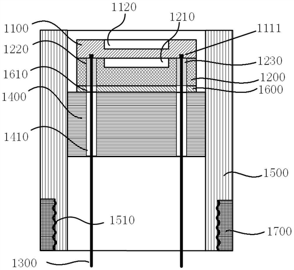
[0047] figure 1 A schematic diagram showing a leadless package structure of a silicon carbide pressure sensor provided by an embodiment of the present invention, the leadless package structure includes: a silicon carbide chip 1100, a silicon carbide cup 1200, a kovar pin 1300, a base 1400, and a metal shell 1500 and the first transition layer 1600. It should be understood that figure 1 It is a schematic cross-sectional view of the leadless package structure of the silicon carbide pressure sensor.

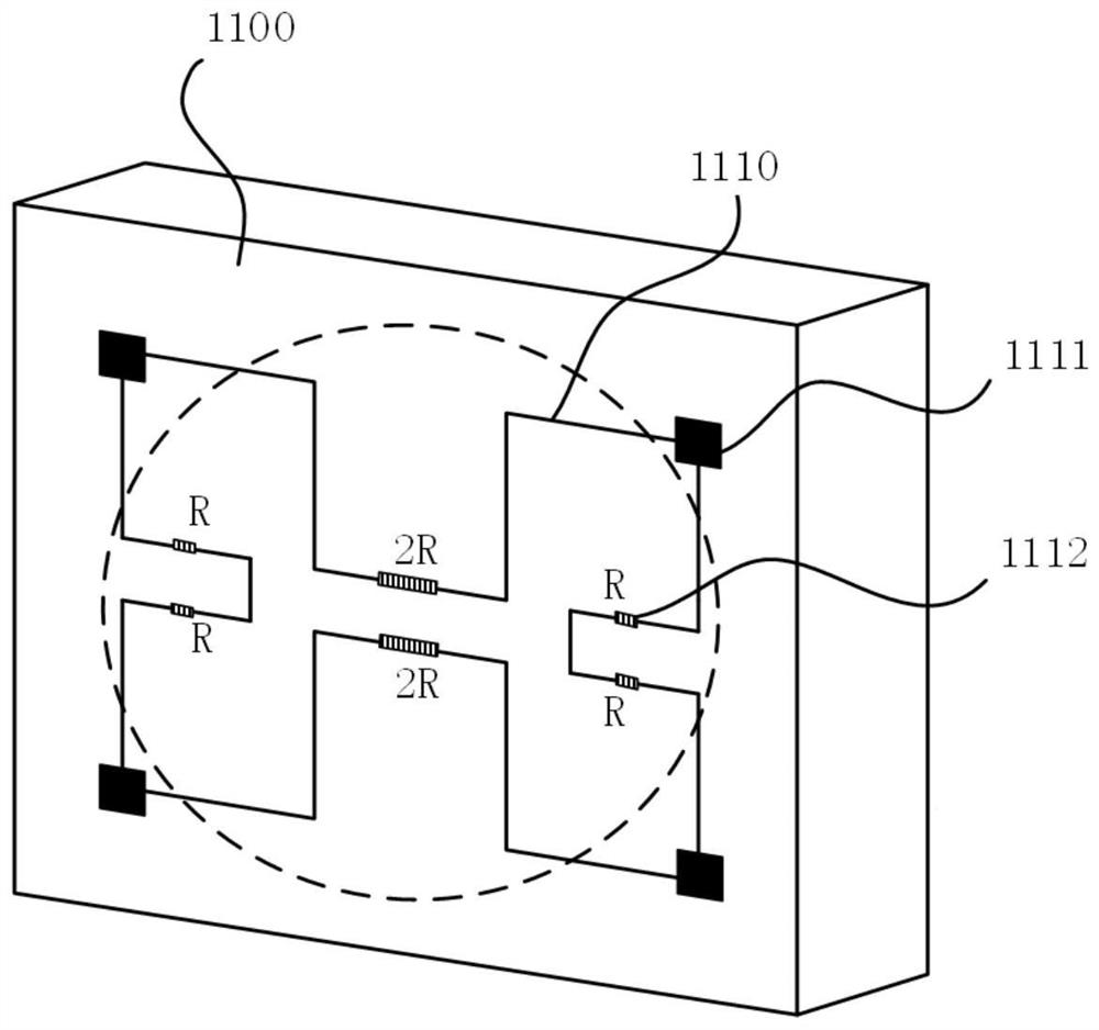
[0048] Such as figure 2 As shown, the silicon carbide chip 1100 includes a first surface and a second surface, and the first surface and the second surface are opposite surfaces. The first surface may be the front surface of the silicon...


PUM


Abstract

The invention discloses a leadless packaging structure and packaging method of a piezoresistive sensor. The packaging structure comprises a silicon carbide chip, a silicon carbide cup, a kovar pin, abase, a metal shell and a first transition layer. A chip circuit is arranged on the front surface of the silicon carbide chip, and a first groove is formed in the back surface of the silicon carbide chip; a second groove is formed in the back surface of the silicon carbide cup; the front surface of the silicon carbide chip and the back surface of the silicon carbide cup are bonded together to forma bonding object; the kovar pin is inserted into the through hole in the silicon carbide cup sequentially through the base and the through hole in the first transition layer and is connected with themetal bonding pad; the bonding object, the base and the kovar pin are combined together through sintering and are fixed in an inner cavity of the metal shell; and the metal shell is fixed on the fixing piece through a thread structure. The high-temperature stability and reliability of the sensor are improved in a leadless packaging mode.

Description

technical field [0001] The invention relates to the technical field of sensor packaging, in particular to a leadless packaging structure and packaging method of a piezoresistive sensor. Background technique [0002] At present, most of the packaging forms of piezoresistive pressure sensors are packaging structures with wire leads. In some applications with relatively harsh conditions, such as high temperature applications (above 600 ° C), the sensor needs to have higher stability and reliability. The traditional wire lead method will bring unpredictable reliability problems, such as wire creep, softening and falling off. The leadless packaging structure will become the development direction of sensor packaging technology. [0003] The traditional wire lead packaging structure seals the front circuit of the sensor chip under the corrugated sheet filled with silicone oil, and the external pressure is indirectly transmitted to the pressure sensor chip through the corrugated sh...

Claims


Application Information

Patent Timeline
Patent Type & Authority Patents(China)
IPC IPC(8): G01L9/06G01L19/06G01L19/00
Inventor 赵友赵玉龙
Owner XI AN JIAOTONG UNIV
Why Eureka
Try Eureka