Eureka AIR delivers breakthrough ideas for toughest innovation challenges, trusted by R&D personnel around the world.

High-vacuum continuous casting forming equipment and process for precious metal layered composite materials

A technology of layered composite materials and forming equipment, applied in the field of continuous casting, can solve problems such as inability to meet process requirements

Active Publication Date: 2021-05-07
UNIV OF SCI & TECH BEIJING
View PDF1 Cites 0 Cited by
  • Summary
  • Abstract
  • Description
  • Claims
  • Application Information

AI Technical Summary

Problems solved by technology

However, the limitation of the conventional one-time continuous casting direct compounding method is that the melting, heat preservation, and casting of metals are all in the atmospheric environment. Even metals with stable chemical properties such as gold and silver cannot meet the requirements of the process when the quality of the finished product is high. Require

Method used


Image

  • High-vacuum continuous casting forming equipment and process for precious metal layered composite materials
  • High-vacuum continuous casting forming equipment and process for precious metal layered composite materials

Examples


Embodiment

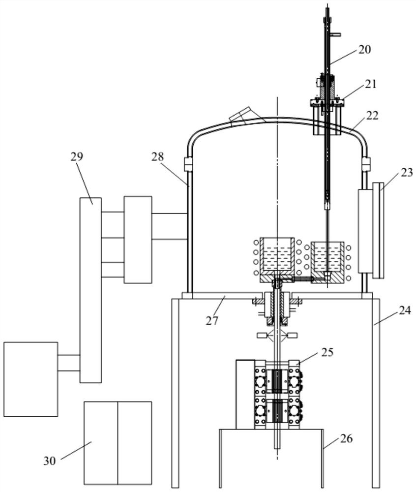
[0062] The invention discloses a continuous casting composite forming process of a silver-clad aluminum composite bar, the diameter of the bar is 20mm, and the thickness of the silver cladding layer is 3mm.

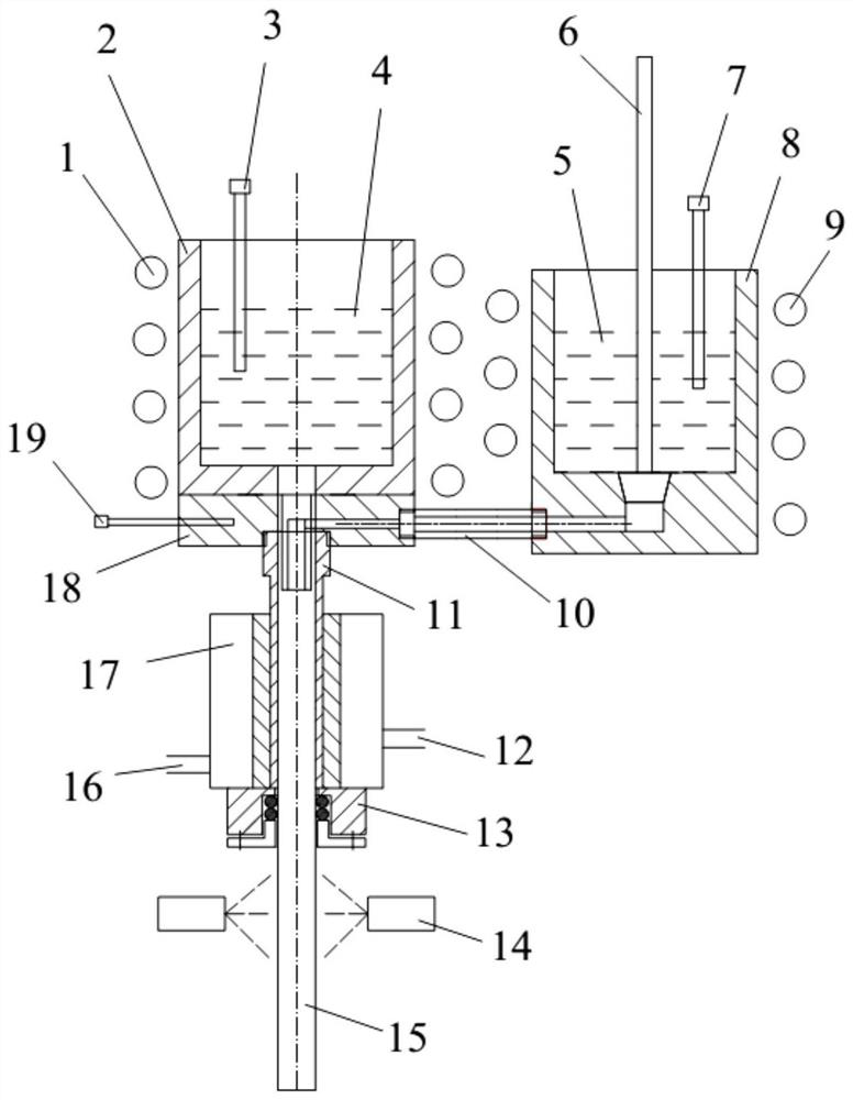
[0063] (1) Assemble the crucible for melting silver and the mandrel device for forming its cladding tube, and then install the assembled crucible into the induction heating coil in the vacuum furnace. Then, install the crucible for melting aluminum into another induction heating coil in the vacuum furnace, and connect the two crucibles through a draft tube. A layer of thermal insulation material should be arranged between the crucible and the heating coil.

[0064] (2) Assemble the composite mold and the crystallizer into a composite device, and then tightly connect the crystallizer to the bottom plate of the vacuum furnace; respectively load two kinds of silver and aluminum into the two crucibles, and install them in the two crucibles and on the composite mold Thermocou...

Embodiment 2

[0068] Embodiment 2: A continuous casting composite forming process of a silver-clad copper alloy composite bar, the diameter of the bar is 20mm, and the thickness of the silver cladding layer is 3mm.

[0069] (1) Assemble the crucible for melting silver and the mandrel device for forming its cladding tube, and then install the assembled crucible into the induction heating coil in the vacuum furnace. Then, install the crucible for melting the AgCu28 alloy into another induction heating coil in the vacuum furnace, and connect the two crucibles through a draft tube. A layer of thermal insulation material should be arranged between the crucible and the heating coil.

[0070] (2) Assemble the composite mold and the crystallizer into a composite device, then tightly connect the crystallizer to the bottom plate of the vacuum furnace; respectively load two kinds of silver and silver-copper alloys into the two crucibles, and place them on the composite mold in the two crucibles Insta...


PUM

PropertyMeasurementUnit
diameteraaaaaaaaaa
thicknessaaaaaaaaaa

Abstract

The invention belongs to the field of continuous casting technology, and in particular relates to a high-vacuum continuous casting forming equipment and process for precious metal layered composite materials. It is composed of device, dummy mechanism, secondary cooling device and auxiliary equipment. The continuous casting process is as follows: equipment assembly and reliable connection; vacuuming the furnace body; heating and melting the two metals; first performing continuous casting of the outer layer metal, and then making the core metal enter the outer layer metal tube, in the composite crystallizer and Under the action of the secondary cooling device, it is solidified and combined with the outer metal. When the continuous casting bar reaches a certain length, it can be sawn off as needed. The advantages are: it can guarantee the high-vacuum continuous casting environment required by precious metals, the smelting and forming of inner and outer metals, and the compounding of bimetallic interfaces are all realized in a state of no oxidation and pollution; the preparation process is short and efficient.

Description

technical field [0001] The invention belongs to the technical field of continuous casting, and in particular provides a bimetal suitable for the melting point of the outer layer metal higher than the melting point of the core metal, especially a bimetal primary casting that requires high smelting and casting conditions, is easy to absorb gas, and is easy to oxidize. High-vacuum continuous casting forming equipment and technology of precious metal layered composite materials for composite forming. [0002] technical background [0003] Precious metal wires such as gold and silver are key materials necessary for the electronic information industry due to their excellent electrical conductivity, welding performance and stability. With the rapid development of the electronic information industry, people have higher and higher requirements for metal wires, with thinner wire diameters, higher conductivity, more suitable strength and stiffness, and lower costs. Traditional single-m...

Claims


Application Information

Patent Timeline
Patent Type & Authority Patents(China)
IPC IPC(8): B22D11/041B22D11/10B22D11/124B22D11/14
Inventor 刘新华谢建新施兵兵谢明
Owner UNIV OF SCI & TECH BEIJING
Why Eureka
Eureka Blog
Learn More