A detection device for electrical automation equipment

A technology of electrical automation and detection devices, which is applied in the direction of measuring devices, measuring heat, and parts of thermometers, etc., which can solve problems such as large functional influence, poor effect, and inaccurate detection data

Active Publication Date: 2020-10-27
IANGSU COLLEGE OF ENG & TECH
View PDF5 Cites 0 Cited by
  • Summary
  • Abstract
  • Description
  • Claims
  • Application Information

AI Technical Summary

Problems solved by technology

[0002] In the production process of the touch function layer inside the touch display screen, the surface of plain glass needs to be cleaned, coated, glued, exposed, developed, baked and cured, etched, and stripped and cleaned in sequence. The function of the control function layer has a great influence on the function. Once the baking and curing effect is poor, it can lead to a sharp increase in the defect rate
[0003] In the existing process, a tunnel furnace is generally used to bake and cure the exposed conductive glass (that is, the plain glass coated with an ITO conductive film layer on the surface). When the tunnel furnace is first installed and used, the heating temperature inside the tunnel furnace needs to be adjusted. Whether it is evenly tested to ensure orderly production operations in the later stage. At the same time, the tunnel furnace is a kind of equipment with a relatively high degree of electrical automation. It is troublesome to check this kind of equipment. The traditional technical solution is to use heat conduction plates with copper wires and analyze It is cumbersome and complicated to detect whether the heating temperature inside the tunnel furnace is uniform. The copper wire is easily wound inside the tunnel furnace, and the detection is often stopped midway due to copper wire breakage, which affects the detection result. At the same time, it can only One of the two heating surfaces inside the tunnel furnace is tested, which makes the detected data inaccurate and cannot guarantee the orderly production operations in the later stage. Therefore, a detection device for electrical automation equipment is proposed

Method used


Image

  • A detection device for electrical automation equipment
  • A detection device for electrical automation equipment
  • A detection device for electrical automation equipment

Examples


Embodiment 1

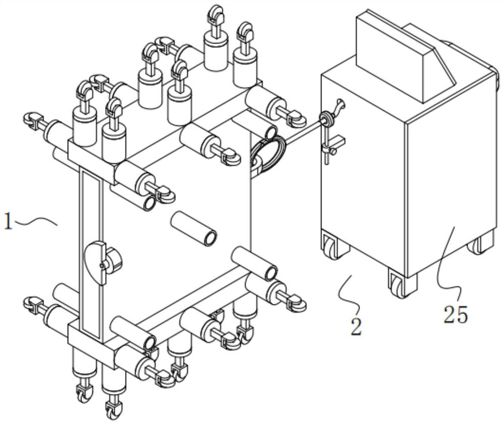
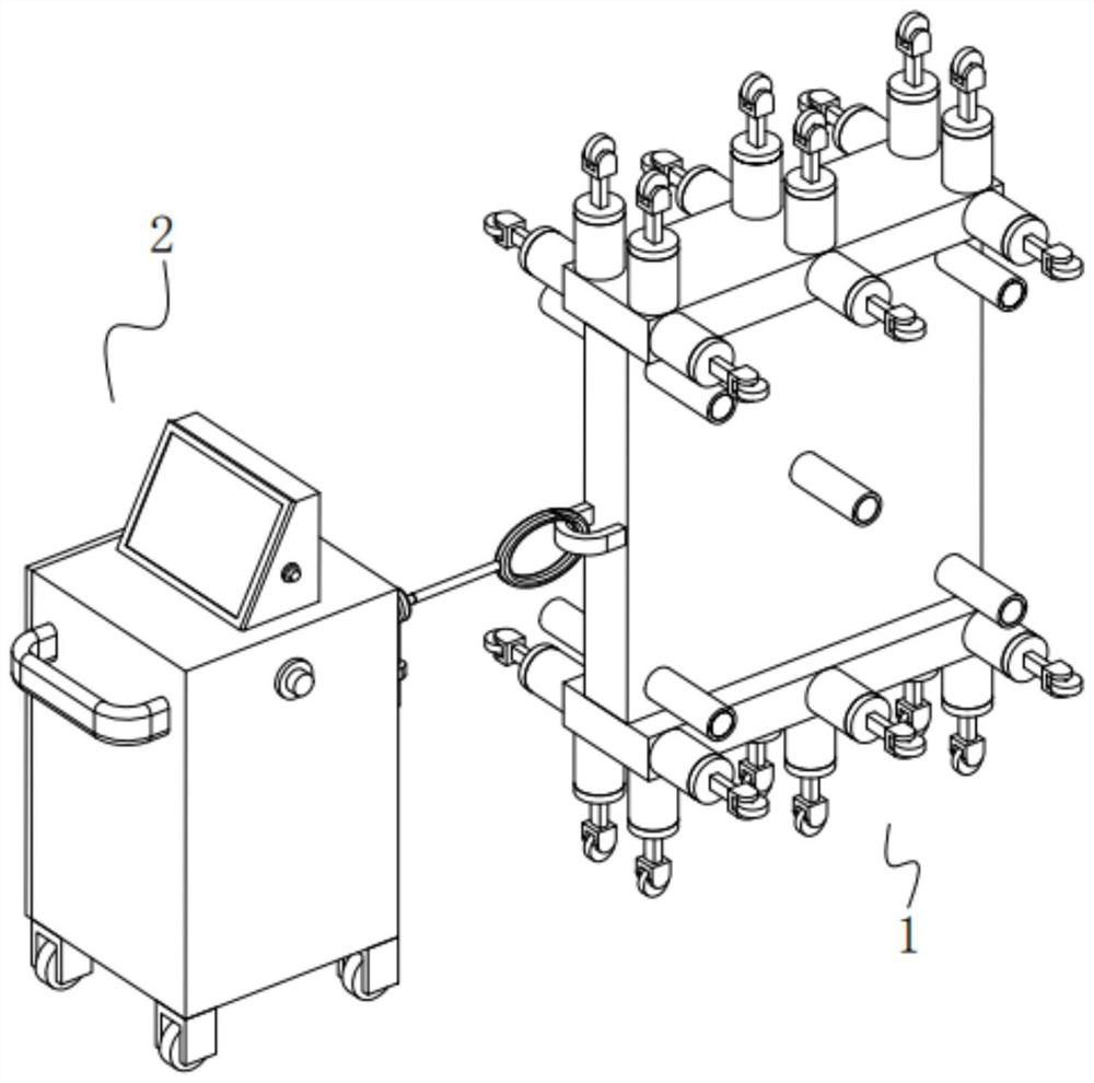
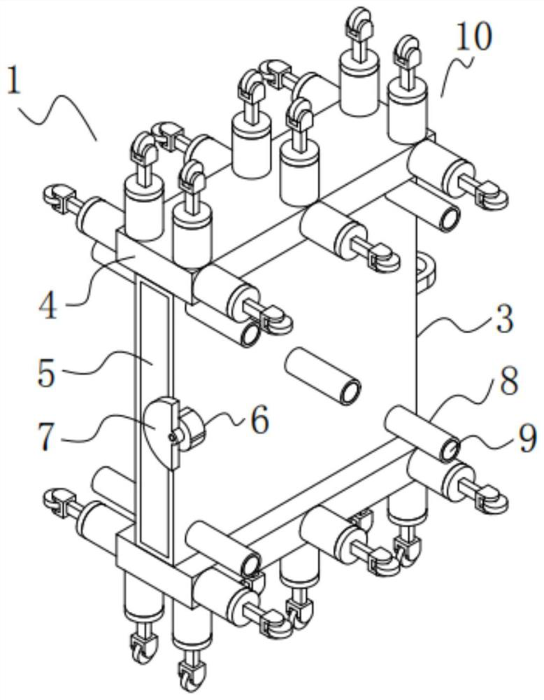
[0055] A detection device for electrical automation equipment, such as Figure 1-3 , 5 and 7, including a detection unit 1, the detection unit 1 includes a square housing 3, two bosses 4, several round tubes 8, several temperature sensors 9, a controller 23, a first storage battery 26, The USB interface 29, the first power switch 20 and the first cover plate 5, the two bosses 4 are symmetrically installed on the top and bottom of the square housing 3, and several of the round tubes 8 are evenly distributed and fixedly installed on the square housing 3. On the two outer sides of the square housing 3, several temperature sensors 9 are respectively fixedly installed inside several of the circular tubes 8, and the first cover plate 5 is movably installed on one side of the square housing 3. On the end face, the controller 23 and the first storage battery 26 are both fixedly installed inside the square housing 3 , and the USB interface 29 and the first power switch 20 are both inst...

Embodiment 2

[0079] The difference from Example 1 is that the surface of the square housing 3 is also provided with a protective layer, and the protective layer is prepared by the following method:

[0080] Take the following raw materials and weigh them by weight: 20 parts of epoxy resin, 8 parts of titanium dioxide powder, 10 parts of ceramic microspheres, 17 parts of magnesium aluminum silicate, 15 parts of vermiculite particles, 13 parts of manganese dioxide particles, 10 parts of copper oxide particles 4 parts, 12 parts of alcohol ester, 3 parts of triethanolamine, 3 parts of emulsified silicone oil and 30 parts of water;

[0081] S1. Add the weighed magnesium aluminum silicate, alcohol ester dodeca, triethanolamine, emulsified silicone oil and water into the mixer and stir for 15 minutes at a stirring speed of 500r / min to prepare a mixed solution;

[0082] S2, adding epoxy resin, titanium dioxide powder, ceramic microbeads, vermiculite particles, manganese dioxide particles and coppe...

Embodiment 3

[0088]The difference with embodiment 2 is the preparation of protective layer, and its specific preparation method is as follows:

[0089] Take the following raw materials and weigh them by weight: 25 parts of epoxy resin, 10 parts of titanium dioxide powder, 12 parts of ceramic microspheres, 20 parts of magnesium aluminum silicate, 18 parts of vermiculite particles, 14 parts of manganese dioxide particles, 12 parts of copper oxide particles 12 parts, 6 parts of alcohol esters, 4 parts of triethanolamine, 4 parts of emulsified silicone oil and 40 parts of water;

[0090] S1. Add the weighed magnesium aluminum silicate, alcohol ester dodeca, triethanolamine, emulsified silicone oil and water into the mixer and stir for 18 minutes at a stirring speed of 600r / min to prepare a mixed solution;

[0091] S2, adding epoxy resin, titanium dioxide powder, ceramic microbeads, vermiculite particles, manganese dioxide particles and copper oxide particles into a pulverizer for pulverization...


PUM

PropertyMeasurementUnit
thicknessaaaaaaaaaa
thicknessaaaaaaaaaa

Abstract

The invention discloses a detection device for electric automation equipment, which comprises a detection part, and the detection part comprises a square shell, two bosses, several round pipes, several temperature sensors, a controller, a first storage battery, and a USB interface And the first power switch and the first cover plate. Compared with the traditional technical solution, the present invention uses a combination of heat conduction plate, copper wire and analyzer to detect whether the heating temperature inside the tunnel furnace is uniform, which is simpler and more convenient, and can effectively prevent the copper wire from winding inside the tunnel furnace. It can also prevent the detection from stopping midway due to copper wire breakage, thereby affecting the detection results. At the same time, the two heating surfaces inside the tunnel furnace are detected separately, and the temperature data of five points are detected on each heating surface, which can more truly reflect the tunnel furnace. Whether the internal heating temperature is uniform will make the detected data more accurate to ensure orderly production operations in the later stage.

Description

technical field [0001] The invention relates to the technical field of electric automation, more specifically, it relates to a detection device for electric automation equipment. Background technique [0002] In the production process of the touch function layer inside the touch display screen, the surface of plain glass needs to be cleaned, coated, glued, exposed, developed, baked and cured, etched, and stripped and cleaned in sequence. The function of the control function layer is greatly affected. Once the baking and curing effect is poor, the defect rate will increase significantly. [0003] In the existing process, a tunnel furnace is generally used to bake and cure the exposed conductive glass (that is, the plain glass coated with an ITO conductive film layer on the surface). When the tunnel furnace is first installed and used, the heating temperature inside the tunnel furnace needs to be adjusted. Whether it is evenly tested to ensure orderly production operations in...

Claims


Application Information

Patent Timeline
Patent Type & Authority Patents(China)
IPC IPC(8): G01K1/14G01K1/10G01K1/12
Inventor 师阳赵斌朱海荣康宜平
Owner IANGSU COLLEGE OF ENG & TECH
Why Eureka
Try Eureka