
Control Device for folding/unfolding Window Shade

a control device and window shade technology, applied in the direction of door/window protective devices, shutters/movable grilles, wing arrangements, etc., can solve the problems of inconvenient use, complicated structure and inconvenient assembly, and the other end of the brake mechanism outside of the headrail and controlled by the pull tape is liable to be damaged or broken

Inactive Publication Date: 2011-12-01
CHENG LI MING
View PDF18 Cites 43 Cited by
  • Summary
  • Abstract
  • Description
  • Claims
  • Application Information

AI Technical Summary

Benefits of technology

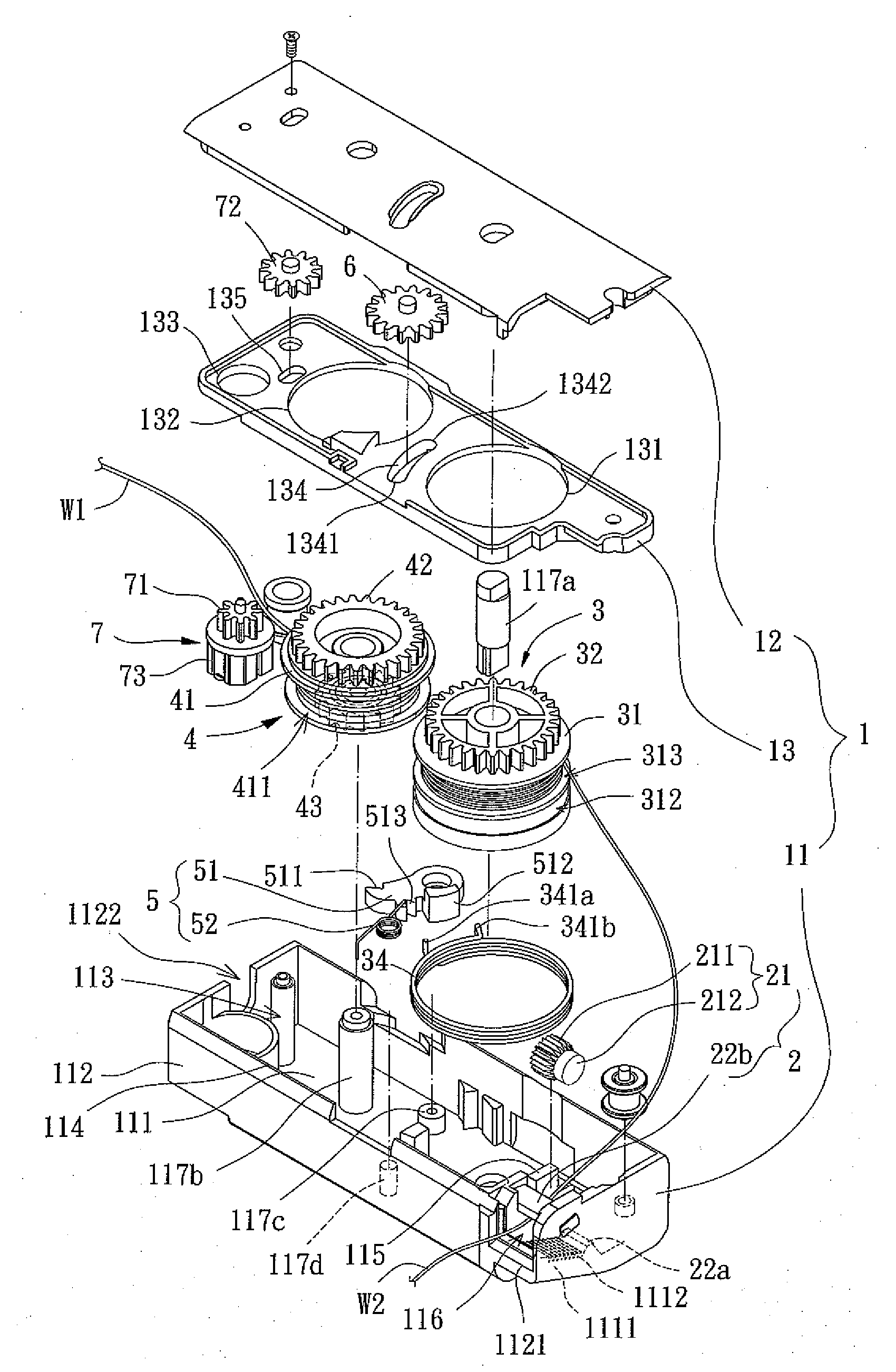
[0015]An objective of the present invention is to provide a control device for folding / unfolding a window shade that controls vertical movement of the window shade by utilizing a single pull cord to avoid entanglement between multiple pull cords.
[0016]Another objective of the present invention is to provide a control device for folding / unfolding a window shade that controls engagement of a clutch unit by utilizing a single pull cord to enhance operational convenience and easiness.
[0017]A further objective of the present invention is to provide a control device for folding / unfolding a window shade that has fewer elements to enhance assembling convenience and to reduce manufacturing costs.
[0021]Thus, folding and unfolding of the window shade can be achieved by operating a single pull cord, providing a simplified structure.

Problems solved by technology

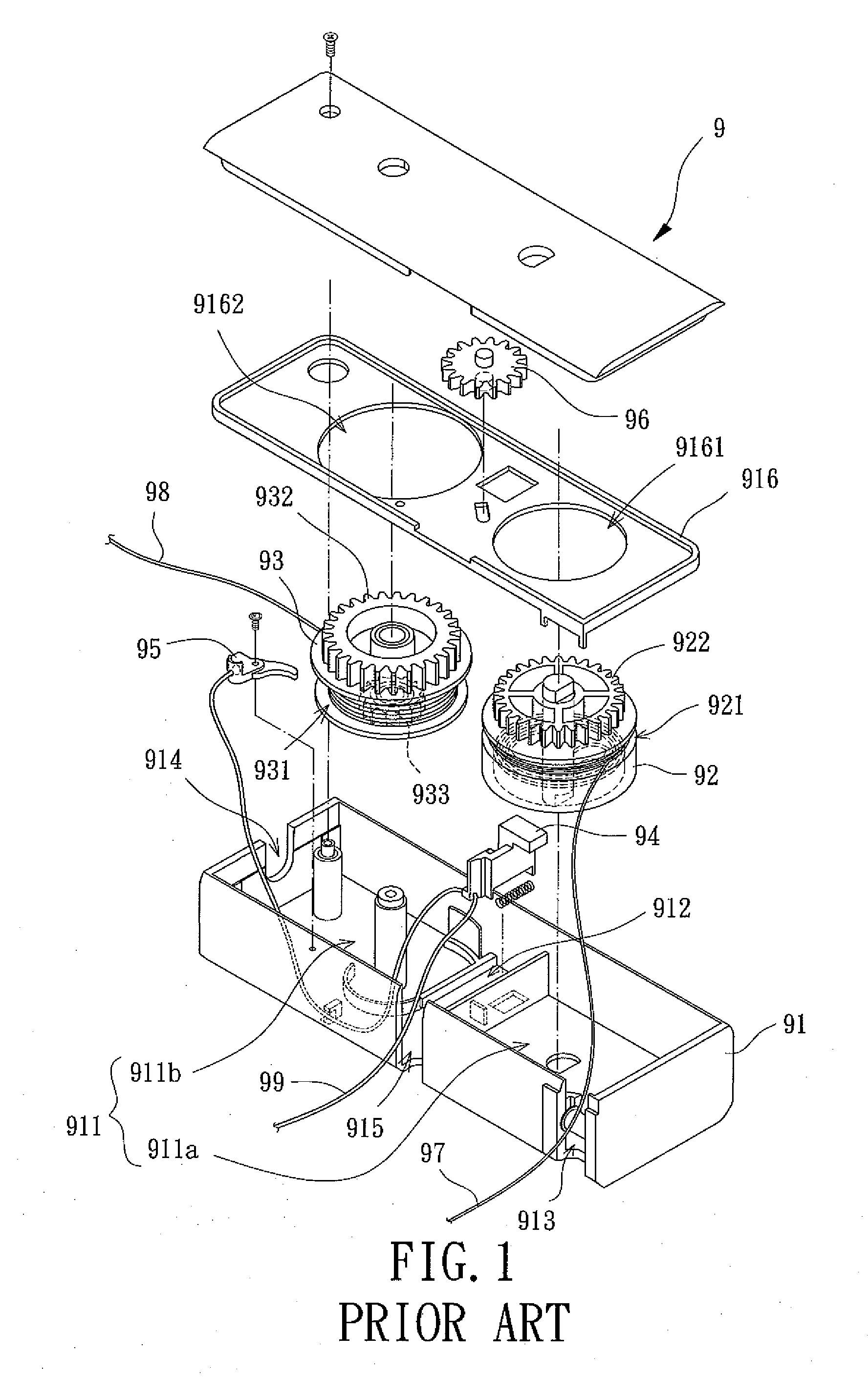
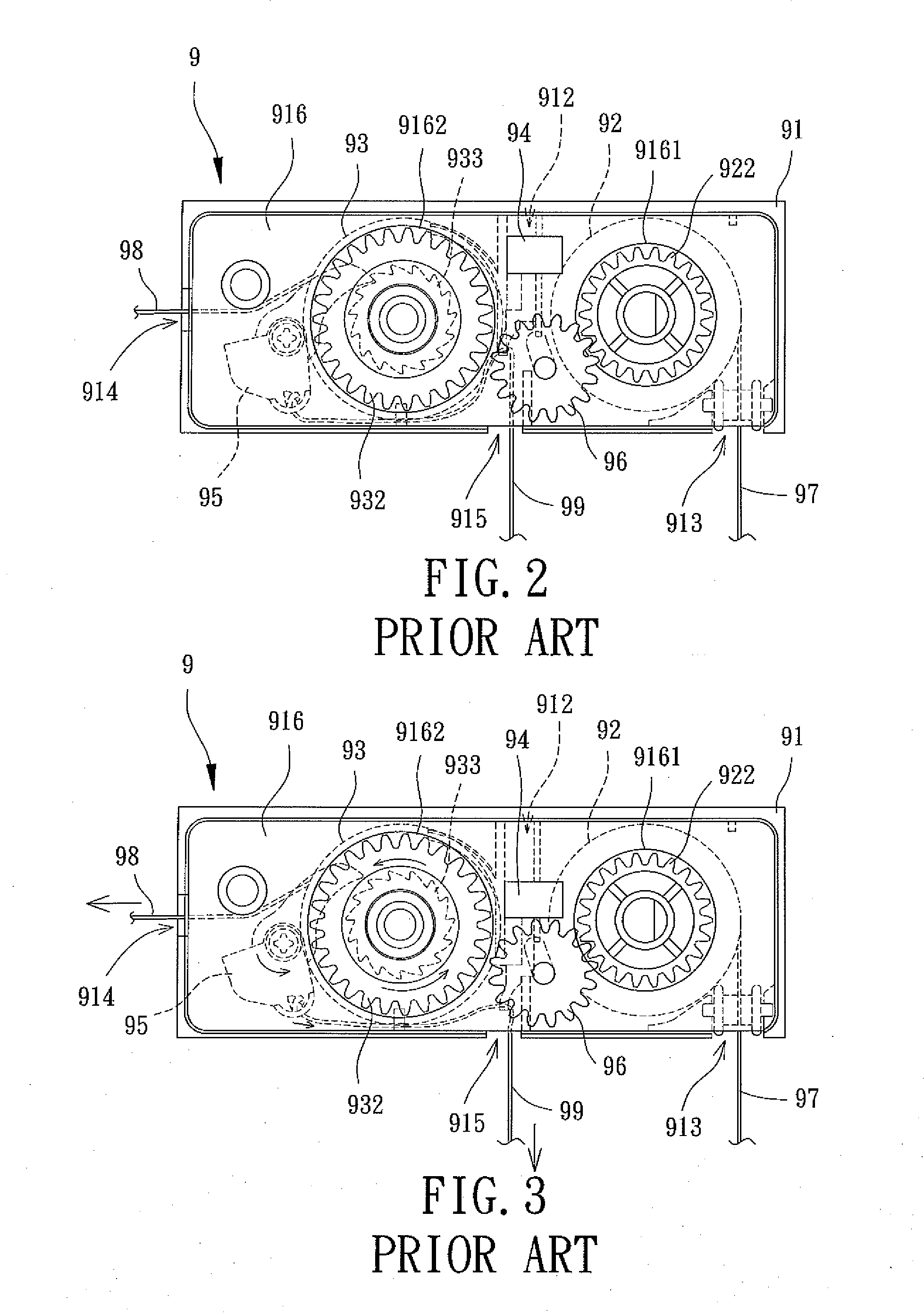
The use has to disentangle the first and second pull cords 97 and 99 before pulling one or both of them, leading to inconvenient use.
Although the rotating direction of the main drive assembly can be restrained by the additional clutch / brake assembly to achieve folding / folding of the covering, the clutch / brake assembly must be operated through the brake mechanism, resulting in a complicated structure and inconvenient assemblage.
Furthermore, the other end of the brake mechanism outside of the headrail and controlled by the pull tape is liable to be damaged or broken by improper pulling or impact by alien objects.

Method used


Image

  • Control Device for folding/unfolding Window Shade
  • Control Device for folding/unfolding Window Shade
  • Control Device for folding/unfolding Window Shade

Examples


Embodiment Construction

[0042]A control device according to the preferred teachings of the present invention can be utilized to control release and winding of a tying cord for folding / unfolding a window shade. The control device according to the preferred teachings of the present invention can be utilized with window shades of various types. FIG. 7 shows an example of the window shades in the form of a vertical shade 8. According to the preferred form shown, the vertical shade 8 includes a shade 81, a headrail 82 mounted to a top of the shade 81, and a bottom rail 83 mounted to a bottom of the shade 81. A cord T is arranged in an inverted U-shaped manner and includes a horizontal section received in the headrail 82 and two vertical sections extending through the shades 81 with two ends of the cord T anchored to bottom rail 83. The control device according to the preferred teachings of the present invention is received in the headrail 82 and includes a tying cord W1 having an end fixed to the horizontal sec...


PUM


Abstract

A control device for folding / unfolding a window shade includes a casing rotatably receiving first and second driving wheels around which a pull cord and a tying cord are wound. The first driving wheel includes a first gear and a pressing member. The second driving wheel includes a second gear and an auxiliary gear. A clutch unit is located between the first and second driving wheels and includes a first end releasably engaged with the auxiliary gear on the second driving wheel and a second end abutting the pressing member. A transmission gear is slideably received in the casing. The pull cord is pullable to a desired extent to control the transmission gear to mesh with the first gear or both of the first and second gears, achieving folding or unfolding of the window shade.

Description

BACKGROUND OF THE INVENTION[0001]1. Field of the Invention[0002]The present invention relates to a control device for folding / unfolding a window shade and, more particularly, to a control device for folding / unfolding a window shade that is simple in structure and easy to operate.[0003]2. Description of the Related Art[0004]Window shades are generally mounted to windows, doorways, or passageways in buildings to shield the light, to provide privacy, and to provide a decoration. A wide variety of window shades including vertical shades, cloth shades, bead shades, etc has been proposed and generally includes a control device to fold / unfold the window shade, providing convenient use.[0005]FIGS. 1-6 show a conventional control device 9 for a window shade. The control device 9 includes a casing 91, a first driving wheel 92, a second driving wheel 93, a slide 94, a clutch unit 95, and a transmission gear 96. The casing 91 includes a compartment 911 divided by a partitioning groove 912 into ...

Claims


Application Information

Patent Timeline
IPC IPC(8): E06B9/24
CPCE06B9/262E06B2009/3222E06B2009/2627E06B9/322
Inventor CHENG, LI-MING
Owner CHENG LI MING
Learn More