


Quick Research
Generate reliable direction feasibility study reports for your R&D in just a few steps.

Technical Q&A
Discover and master advanced knowledge NOW. Basics, ideas, possibilities, all at once.

Find Solutions
As an expert in R&D theories, this can generate solutions to your technical problems instantly.

Evaluate Feasibility
Analyze your overall solution with one click, know your potential R&D risks in advance.

Monitor Landscape
Get weekly tech updates, stay abreast of the latest tech innovations and key insights.
Method for repairing fatigue cracks by cold spraying
A fatigue cracking and cold spraying technology, applied in pressure inorganic powder coating and other directions, can solve the problems of stress concentration in deteriorated and strengthened parts, reduction of static strength of components, instability and other problems, and achieve the effect of eliminating stress concentration and prolonging extended life.
- Summary
- Abstract
- Description
- Claims
- Application Information
AI Technical Summary
Problems solved by technology
Method used
Image


Examples
Embodiment 1
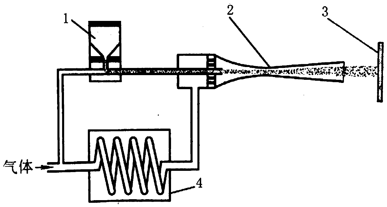
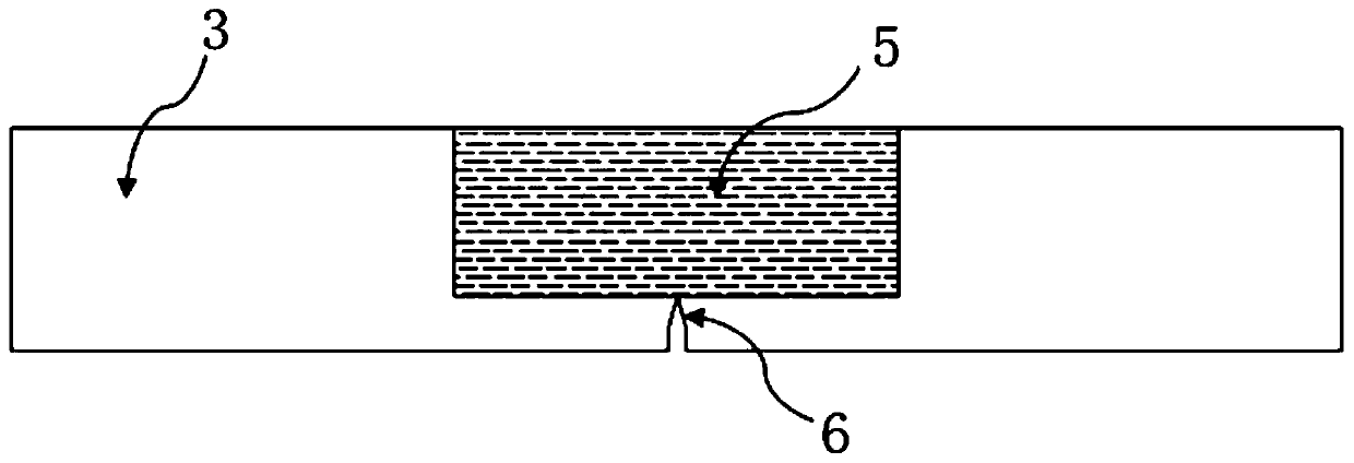
[0042] The fatigue test is carried out by making a standard single-side notched three-point bending specimen, such as Figure 2 ~ Figure 4 . First, the surface of the sample is polished with 100 mesh, 500 mesh, 1000 mesh and 1500 mesh sandpaper in sequence, then alcohol cleaning and sandblasting, and the aluminum powder with a particle size of 15±5μm is passed through the high pressure gas by the powder feeder 1 through the gas heater After 4, it is accelerated and sent to the Laval nozzle 2, and the aluminum powder is deposited on the surface of the substrate 3 to complete the repair and strengthening. Specific parameters used in cold spraying: main force air pressure 1.0MPa, powder feeding rate 15g / min, distance between spraying and substrate 12mm, spraying moving speed 15mm / s, gas heating temperature 300°C. The cold sprayed aluminum coating is 3mm thick and sanded to 2mm with 3000 grit sandpaper. Then, put the standard unilateral notched three-point bending specimen repai...
Embodiment 2
[0044] The fatigue test is carried out by making a standard single-side notched three-point bending specimen, such as Figure 2 ~ Figure 4 . First, the surface of the sample is polished with 100 mesh, 500 mesh, 1000 mesh and 1500 mesh sandpaper in sequence, then cleaned with alcohol, and sandblasted with corundum sand, and the A5052 aluminum alloy powder with a particle size of 15±5 μm is fed by the powder feeder 1 The high-pressure gas is accelerated into the Laval nozzle 2 after passing through the gas heater 4, and the aluminum powder is deposited on the surface of the substrate 3 to complete the repair and strengthening. Specific parameters used in cold spraying: main force air pressure 1.0MPa, powder feeding rate 16g / min, distance between spraying and substrate 15mm, spraying moving speed 10mm / s, gas heating temperature 350°C. The thickness of the cold-sprayed aluminum coating is 3mm, and it is sanded to 2mm with 3000-grit sandpaper. Then, put the standard unilateral no...
PUM
 Abstract
Description
Claims
Application Information
 - R&D Engineer
- R&D Manager
- IP Professional
- Industry Leading Data Capabilities
- Powerful AI technology
- Patent DNA Extraction
Browse by: Latest US Patents, China's latest patents, Technical Efficacy Thesaurus, Application Domain, Technology Topic, Popular Technical Reports.
© 2024 PatSnap. All rights reserved.Legal|Privacy policy|Modern Slavery Act Transparency Statement|Sitemap|About US| Contact US: help@patsnap.com