Laser cladding repairing method for shaft parts

A technology of laser cladding and repair method, applied in laser welding equipment, furnace type, coating and other directions, can solve the problems of uneven surface size of shaft, rapid repair of unfavorable shaft, reduction of diameter size, etc., to achieve rapid remanufacturing repair, Low cost and small heat affected zone

Pending Publication Date: 2022-04-22
CSR ZHUZHOU ELECTRIC CO LTD
View PDF15 Cites 2 Cited by
  • Summary
  • Abstract
  • Description
  • Claims
  • Application Information

AI Technical Summary

Problems solved by technology

The ultrasonic rolling process will lead to a reduction in the diameter size. Considering the dimensional error of the shaft and the processing error of the device, it is easy to have uneven final size of the shaft surface and deformation of the shaft surface.
[0010] The above existing technical solutions require multiple replacement of processing methods during the entire processing process, so it may need to be realized through repeated disassembly and assembly. The process is very cumbersome, which is not conducive to the rapid repair of the shaft, and it is easy to cause damage to the shaft surface during the disassembly process; Or it is necessary to integrate multiple processing modules on the equipment, the equipment cost is high, and the parameters are difficult to control

Method used


Image

  • Laser cladding repairing method for shaft parts
  • Laser cladding repairing method for shaft parts
  • Laser cladding repairing method for shaft parts

Examples


Embodiment Construction

[0035] In order for those skilled in the art to fully implement the content of the present invention, the content of the present invention will be further described below in conjunction with the drawings and specific embodiments.

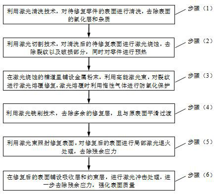
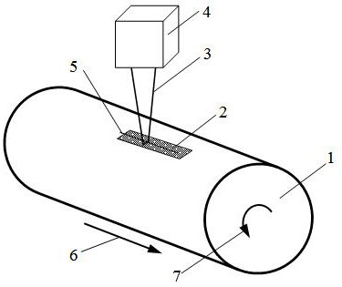
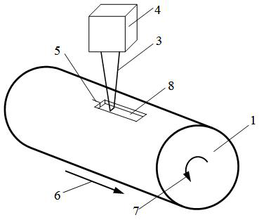
[0036] Such as figure 1 As shown, the entire repair process is divided into the following steps. The pre-treatment steps include cleaning and cutting. The cleaning is to remove the oxide layer and impurities on the surface of the part to be repaired. The cutting is to remove the cracks and surrounding damaged parts of the part to be repaired. , to form the cut channel, after the pretreatment step, the following steps are also included:

[0037] Laser cladding: Lay metal powder in the channel, and use high-energy laser beams to repair the cracks by laser cladding to form a repaired surface;

[0038] Laser annealing: Use laser irradiation to repair the surface, and perform local laser annealing on the repaired surface to remove residual stress;

[0...


PUM

PropertyMeasurementUnit
widthaaaaaaaaaa
depthaaaaaaaaaa
diameteraaaaaaaaaa

Abstract

The shaft part laser cladding repair method comprises pretreatment, the pretreatment comprises cleaning and cutting, the cleaning is to remove an oxide layer and impurities on the surface of a to-be-repaired part, the cutting is to remove cracks and peripheral damaged parts of the to-be-repaired part to form a cut channel, and after the pretreatment, the to-be-repaired part is subjected to laser cladding. Metal powder is laid in the channels, laser cladding repairing is conducted on the cracks through high-energy laser beams, and a repaired surface is formed; laser annealing is conducted, specifically, the surface is repaired through laser irradiation, local laser annealing treatment is conducted on the repaired surface, and residual stress is removed; laser shock treatment is conducted on the repaired surface, residual stress is further removed, and the quality of the repaired surface is strengthened. Local annealing is adopted, so that a heat affected zone is small, and the service life of other parts of the part is not affected; and after laser shock is finished, residual compressive stress is formed on the surface of the cladding layer and counteracts thermal stress generated during laser cladding, and the overall residual stress of the repairing layer is reduced.

Description

technical field [0001] The invention relates to the field of surface crack repair of shaft parts, in particular to a laser cladding repair method for shaft parts. Background technique [0002] With the rapid development of rail transit, the operation and maintenance requirements and technical level of rail vehicles are increasing day by day. Traction motor is an important part of rail transit. During operation, due to factors such as heavy load, alternating, and complex stress, the traction motor shaft fails. Directly scrapping the motor shaft with cracks will cause a waste of resources, which does not meet the requirements of my country's green development and green manufacturing. [0003] Laser cladding remanufacturing technology is an effective repair technology for traction motor shafts. It can significantly improve the wear resistance, corrosion resistance, heat resistance and oxidation resistance of the surface of the repair layer without affecting the properties of t...

Claims


Application Information

Patent Timeline
Patent Type & Authority Applications(China)
IPC IPC(8): C23C24/10C21D1/30C21D1/34C21D9/28C21D10/00C23F17/00B23K26/38
CPCC23C24/103C23C24/106C21D1/30C21D9/28C21D1/34C21D10/005C23F17/00B23K26/38
Inventor 申政唐子谋肖剑雄汤黎明王继邠杨敏
Owner CSR ZHUZHOU ELECTRIC CO LTD
Why Eureka
Try Eureka