Boiler circulation heat conduction structure

A heat-conducting structure and boiler technology, applied in steam boilers, lighting and heating equipment, steam generation, etc., can solve the problems of insufficient combustion waste heat recovery of burners, large boiler heat loss, and difficult boiler processing, etc., to reduce processing costs , increase the utilization rate, reduce the effect of processing difficulty

Inactive Publication Date: 2019-04-23
刘文国
View PDF1 Cites 0 Cited by
  • Summary
  • Abstract
  • Description
  • Claims
  • Application Information

AI Technical Summary

Problems solved by technology

However, the shape and structure of the boiler is difficult to process, the pressure resistance is poor, and the heat loss of the boiler is large, and the combustion waste heat recovery of the burner is insufficient.

Method used


Image

  • Boiler circulation heat conduction structure

Examples


Embodiment Construction

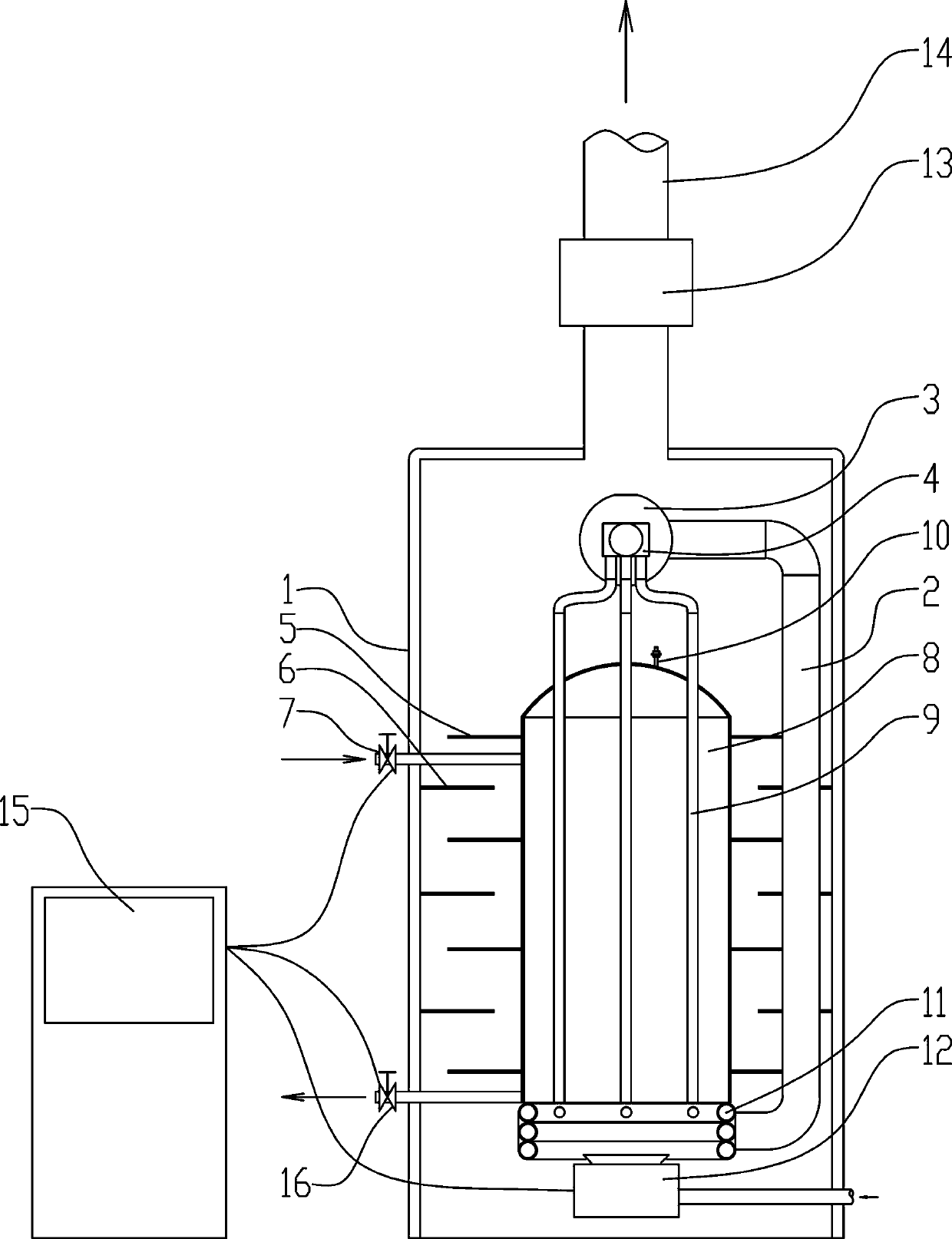
[0014] Such as figure 1 Among them, a boiler circulation heat conduction structure, including a heat collection chamber 11, a heat exchange tube 9 and a circulation pipe 2; at the bottom of the boiler body 8, above the heating device 12, a heat collection chamber 11 is provided, and the inner cavity of the heat collection chamber 11 The body is provided with a heat conducting medium; the heat collecting chamber 11 communicates with at least one heat exchange tube 9, the heat exchange tube 9 passes through the boiler body 8 and communicates with the circulation pipe 2, and the circulation pipe 2 communicates with the heat collection chamber 11, and the circulation pipe 2 is provided with There is a circular drive. With this structure, the heating device 12 heats the heat conducting medium in the heat collecting chamber 11 while heating the bottom of the boiler body 8 , and the flow of the heat conducting medium transfers heat to the water. In this example, the heating device 1...


PUM


Abstract

The invention provides a boiler circulation heat conduction structure. A heat gathering cavity, heat exchange pipes and a circulation pipe are included. The part, above a heating device, at the bottomof a boiler body is provided with the heat gathering cavity, and heat conduction media are arranged in an inner cavity of the heat gathering cavity. The heat gathering cavity communicates with at least one heat exchange pipe, the heat exchange pipes penetrate through the boiler body and communicate with the circulation pipe, and the circulation pipe communicates with the heat gathering cavity. The circulation pipe is provided with a circulation drive device. Through the arrangement of the structure of the heat gathering cavity, the structure of a double-layer water cavity in the prior art iseliminated, and the machining difficulty is lowered; by adoption of the common cylinder and circular-roof boiler structure, the pressure bearing capability of a boiler can be better improved, and themachining cost is greatly reduced. Through the arranged heat gathering cavity, flames of the heating device can be centralized at the bottom of the boiler body, and the fuel utilization rate is increased. In the preferable scheme, a circulation pump is arranged so that the heat exchange pipes can be rapidly utilized for conducting heat to water in the boiler body, and heat generated during combustion of the heating device is further sufficiently utilized.

Description

technical field [0001] The invention relates to the field of boiler equipment, in particular to a boiler circulation heat conduction structure. Background technique [0002] Existing boiler equipment all adopts heating device to heat the boiler body so that the water in the boiler body is heated to generate water vapor. With the rise of energy prices and the improvement of environmental protection requirements, it is necessary to reduce carbon emissions and improve energy efficiency. [0003] Chinese patent document CN 101871688 A describes a heat pipe boiler. This heat pipe boiler includes a cylindrical pot shell and a cylindrical furnace inside the pot shell. A furnace body water chamber is formed between the furnace gall and the pot shell. , a furnace is formed inside the furnace, and an inner water box is arranged on the upper part of the furnace, and the inner cavity of the inner water box communicates with the water chamber of the furnace body through a connecting pip...

Claims


Application Information

Patent Timeline
Patent Type & Authority Applications(China)
IPC IPC(8): F22B31/08
CPCF22B31/08
Inventor 刘文国
Owner 刘文国
Why Eureka
Try Eureka