Quicksand type rotating viscous damper

A viscous damper and damper technology, used in liquid shock absorbers, building components, shockproof and other directions, can solve problems such as unreachable, insufficient spring stiffness, top dead, etc., to improve control efficiency, improve seismic effect, structure simple form effect

Inactive Publication Date: 2019-04-23
TONGJI UNIV
View PDF5 Cites 3 Cited by
  • Summary
  • Abstract
  • Description
  • Claims
  • Application Information

AI Technical Summary

Problems solved by technology

[0004] However, the current viscous dampers still have certain deficiencies: (1) The early viscous dampers are usually in the form of a single rod. When the piston moves, because the volume of the viscous fluid in the cylinder is actually a compressible material, As a result, when the piston rod is pulled out, the volume occupied by the extracted part of the piston rod in the cylinder cannot be compensated immediately, and a vacuum phenomenon will be generated in the cylinder, so that the piston rod cannot continue to move; The viscous fluid part of the oil cylinder on the other side enters the oil cylinder, but the volume of the oil cylinder does not increase, which leads to the top dead phenomenon; (2) It is known from the test that the damping force of the damper under the small stroke condition cannot reach The performance given by the theoretical formula of the damper cannot provide a very high damping ratio as calculated by the theoretical formula when the displacement is small under the action of an earthquake. There is a very obvious phenomenon similar to the lack of spring stiffness in series with the spring, which cannot be expressed. purely viscous mechanical behavior

Method used


Image

  • Quicksand type rotating viscous damper
  • Quicksand type rotating viscous damper
  • Quicksand type rotating viscous damper

Examples


Embodiment Construction

[0025] The invention provides a quicksand type rotary viscous damper.

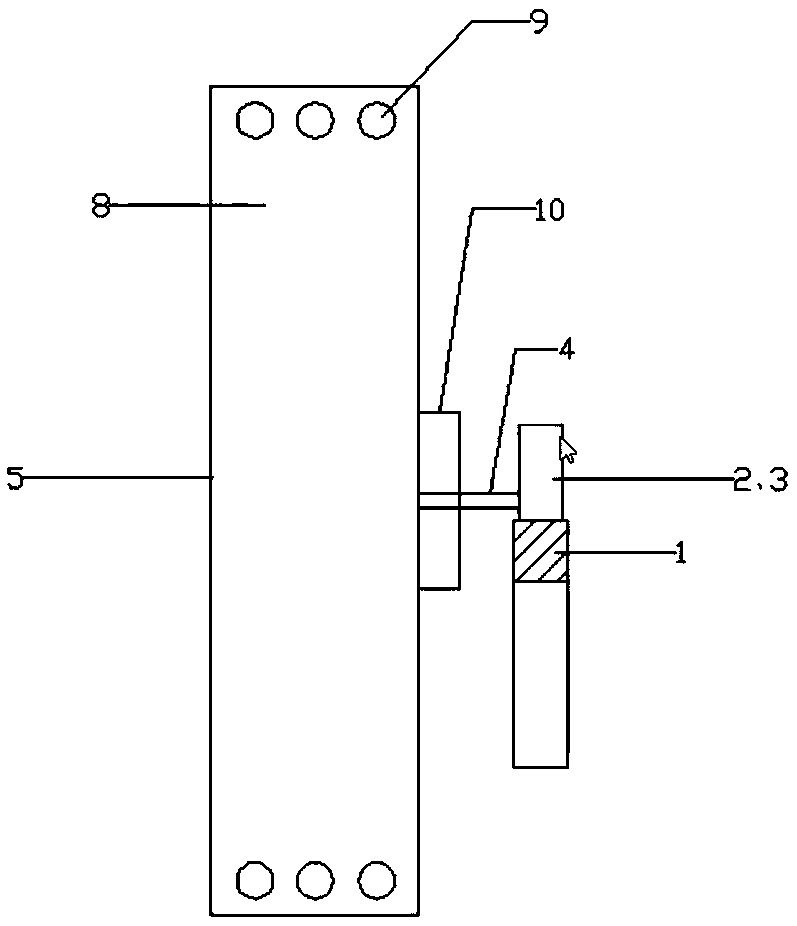
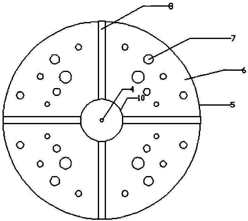
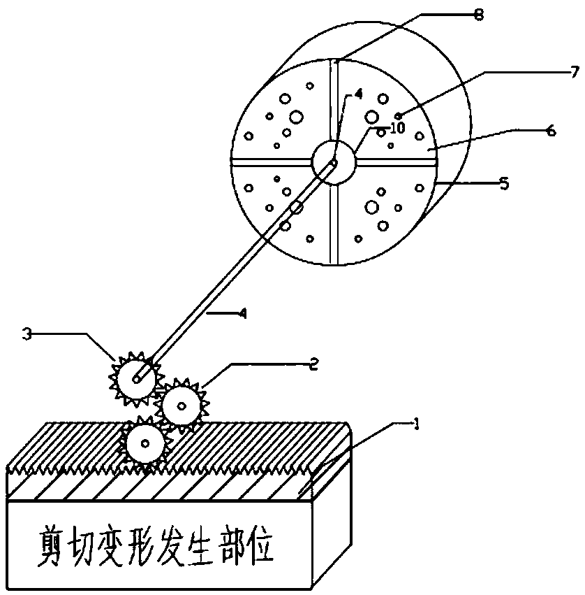
[0026] Such as Figure 1 to Figure 3 As shown, a quicksand type rotary viscous damper includes three parts: the viscous damper body, the displacement velocity input device and the gear transmission amplification device. Input, and transmit the relative displacement and velocity to the viscous damper body through the gear transmission amplification device; specifically, the viscous damper body includes the damper cavity 5, the rotating blade 8, the flow hole 9 and the bearing 10, and the damper cavity The body 5 includes sandy soil viscous liquid mixture 6, several balls or pebbles 7, the rotating blade 8 is installed in the damper cavity 5, the damper cavity 5 is connected with the rotating shaft 4 through the bearing 10, the rotating blade 8 is connected to the transmission The pinion 3 rotates coaxially on the rotating shaft 4, and the radius of the rotating blade 8 is larger than that of the driving pi...


PUM


Abstract

The invention provides a quicksand type rotating viscous damper. Inter-floor relative displacement generated under the earthquake action is input through a displacement speed input device, the relative displacement and the speed are transmitted to a viscous damper body through a gear transmission amplifying device, rotating blades in the viscous damper body are arranged in a damper cavity, the damper cavity is connected with a rotating shaft through a bearing, the rotating blade and a transmission small gear coaxially rotate on the rotating shaft, the radius of the rotating blade is larger than that of the transmission small gear, circulation holes are distributed in the edge of the rotating blade, an input gear in the displacement speed input device is engaged with the transmission smallgear in a gear set, a damper connecting part in the gear transmission amplifying device is composed of the transmission small gear and the rotating shaft, the transmission small gear is engaged with the gear assembly and is fixed to the rotating shaft, the gear transmission principle can be used, linear displacement and linear speed of the edge of the rotating blade are amplified, energy consumption is increased, and the better vibration reduction effect is achieved

Description

technical field [0001] The invention belongs to the technical field of civil engineering (including high-rise buildings, high-rise structures, etc.), and specifically relates to a quicksand-type rotary viscous damper with an assembled amplification device, which combines a viscous damper, a gear transmission type, and a displacement of a rotating blade. The advantage of speed amplification is that it integrates a tuned liquid damper, a tuned mass damper, a viscous damper and a particle damper, thereby effectively improving the shock absorption effect of the viscous damper. Background technique [0002] In recent years, passive control technologies such as base isolation, energy dissipation, and tuned vibration control have been widely used in civil engineering at home and abroad because of their simple concept, clear mechanism, low cost, and remarkable shock absorption effect. Among them, the viscous damper has attracted the attention of civil engineering researchers due to ...

Claims


Application Information

Patent Timeline
Patent Type & Authority Applications(China)
IPC IPC(8): F16F9/12E04B1/98
CPCE04B1/98F16F9/12
Inventor 李依文李培振鲁正
Owner TONGJI UNIV
Why Eureka
Try Eureka