
Automatic fluorescent immunoassay system and method

A fluorescent immunoassay, fully automatic technology, applied in the field of automatic fluorescent immunoassay system, can solve problems such as impact, fuzzy positive and negative class boundaries, inaccurate photon counting, etc., to achieve accurate counting, accurate concentration information, and avoid omissions Effect

Pending Publication Date: 2019-04-02
湖北中医药高等专科学校
View PDF5 Cites 3 Cited by
  • Summary
  • Abstract
  • Description
  • Claims
  • Application Information

AI Technical Summary

Problems solved by technology

[0004] (1) The photon counting of the existing automatic fluorescent immunoassay system is inaccurate, resulting in the inability to obtain accurate fluorescence intensity and lifetime; at the same time, the accurate concentration of reagent compounds cannot be obtained
[0005] (2) In the prior art, after reading the reagent type and sample number information through the barcode reader, traditional algorithms are used to classify various reagent data, resulting in overall changes in the distribution of unbalanced data sets and fuzzy positive and negative class boundaries, reducing classification effect
[0006] (3) In the prior art, when the fluorescence detection module detects the fluorescence signal generated on the sample through the optical detector, the noise generated by the photodetector affects the sensitivity of the fluorescence detection system, reducing the information integrity and time-shift invariance
[0007] (4) Through integration and nonlinear least squares fitting in a specific interval of the photon number time expansion curve, the fluorescence intensity and fluorescence lifetime are obtained respectively, and the nonlinear least squares is easily affected by the initial value during the fitting process The impact of the global search ability is reduced, and no good results can be obtained.

Method used


Image

  • Automatic fluorescent immunoassay system and method
  • Automatic fluorescent immunoassay system and method
  • Automatic fluorescent immunoassay system and method

Examples


Embodiment Construction

[0052] In order to further understand the content, features and effects of the present invention, the following examples are given, and detailed descriptions are given below with reference to the accompanying drawings.

[0053] The structure of the present invention will be described in detail below in conjunction with the accompanying drawings.

[0054] Such as figure 1 As shown, the fully automatic fluorescent immunoassay system detection method provided by the present invention comprises the following steps:

[0055] S101: First, provide power for the automatic fluorescent immunoassay system;

[0056] S102: collecting experimental reagents, numbering the samples, and fluorescently labeling the reagents, using an excitation light source to excite fluorescent signals on the samples;

[0057] S103: use the optical detector to detect the fluorescence signal generated on the sample to calculate the number of photons, and integrate and nonlinear least squares fitting through a ...


PUM


Abstract

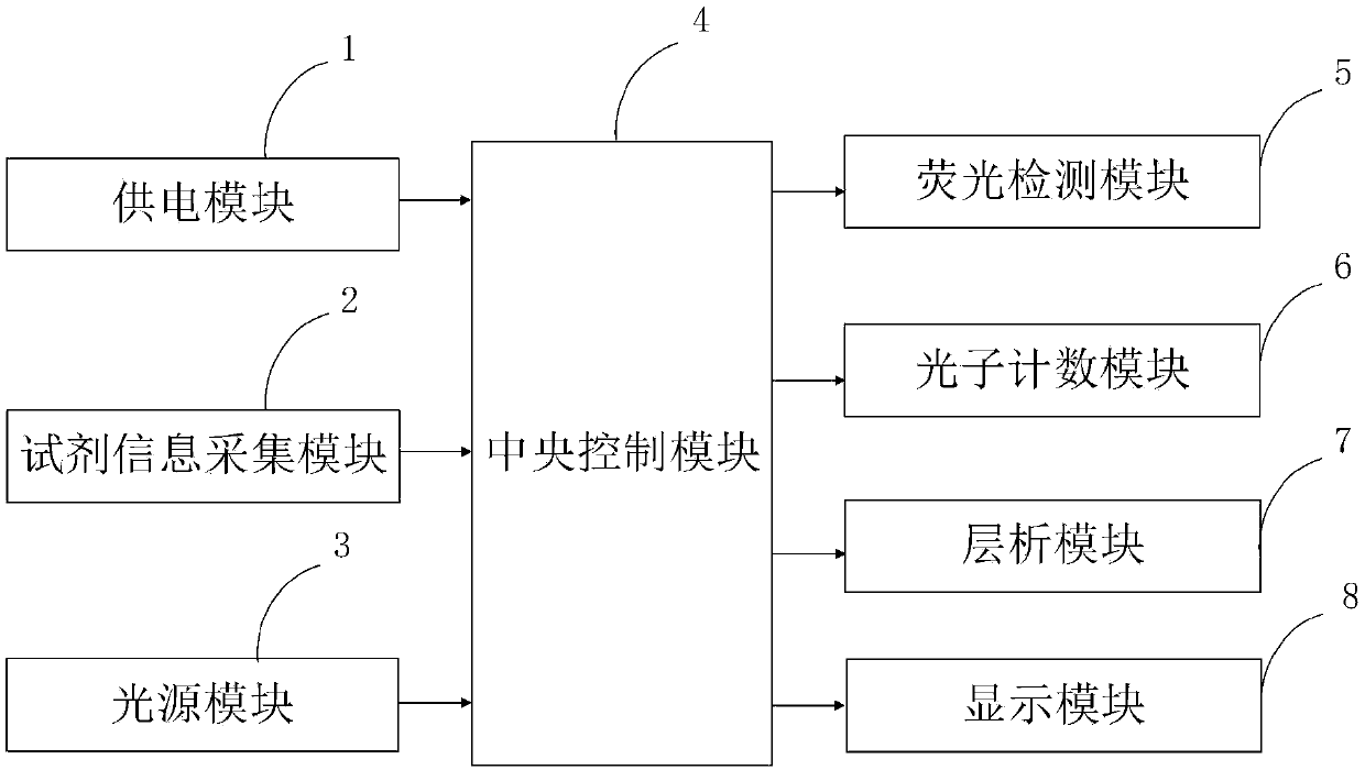
The invention belongs to the technical field of fluorescence immunoassay and discloses an automatic fluorescence immunoassay system and method. The system comprises a power supply module, a reagent information collection module, a light source module, a central control module, a fluorescence detection module, a photon counting module, a chromatography module, and a display module. The invention can effectively avoid the omission phenomenon of photons due to the limitation of a synchronous clock signal in a normal counting mode, and the counting is accurate. In addition, more accurate target compound concentration information can be obtained by the chromatography module. The invention obtains fluorescence intensity and fluorescence lifetime respectively by performing integration and nonlinear least square fitting on a certain interval of a photon number time expansion curve. In order to avoid the influence of an initial value, improve the global search ability and obtain better resultsin the process of fitting the nonlinear least square, a least square algorithm based on a genetic simulated annealing algorithm is adopted.

Description

technical field [0001] The invention belongs to the technical field of fluorescent immunoassay, and in particular relates to a fully automatic fluorescent immunoassay system and method. Background technique [0002] Fluorescence immunoassay technology has the advantages of strong specificity, high sensitivity, and good practicability, so it is used to measure biologically active compounds with very low levels, such as proteins (enzymes, receptors, antibodies), hormones (steroids, Thyroid hormones, phthalein hormones), drugs and microorganisms, etc. Immunoassay is a method of detecting poison by using the competitive binding antibody between poison and labeled poison. It can be used for screening tests of certain toxic drugs. Immunoassay is used for detection. When no non-labeled toxic drug is added, the antibody completely combines with the labeled toxic drug to form a labeled toxic drug-antibody complex. After the non-labeled toxic drug is added, the non-labeled toxic dr...

Claims


Application Information

Patent Timeline
IPC IPC(8): G01N33/533G01N21/64G06K9/62G06N3/12
CPCG06N3/126G01N21/6428G01N33/533G01N2021/6439G06F18/23213G06F18/24323
Inventor 魏琼彭晨月
Owner 湖北中医药高等专科学校
Learn More