A solar cell light attenuation machine

A technology of solar cells and light attenuation machines, applied in circuits, photovoltaic power generation, electrical components, etc., can solve the problems of uneven light source irradiation, low space utilization rate, and small number of cells, so as to achieve uniform light source irradiation and space utilization High efficiency and good installation stability

Active Publication Date: 2020-06-09
HENGDIAN GRP DMEGC MAGNETICS CO LTD
View PDF1 Cites 0 Cited by
  • Summary
  • Abstract
  • Description
  • Claims
  • Application Information

AI Technical Summary

Problems solved by technology

[0003] However, the light source of the equipment used for light attenuation testing on the market is usually located directly above the cell, and the cell is tiled under the light source. The position of the cell and the light source are relatively fixed, and the phenomenon of uneven light source irradiation and poor heat dissipation is common. As a result, the test effect is poor and the reliability is low.
At the same time, the cells can only be tiled under the light source, the number of cells in a single experiment is small, and the space utilization rate is low
[0004] For example, the Chinese patent announcement number is: CN106783665A, a solar cell light attenuation machine announced on May 31, 2017, which includes a frame, a light source box, a lamp, and a solar cell support plate; wherein, the light source box is set on the top of the frame; the lamp is installed on the top of the light source box; the solar cell plate is installed on the frame, and it is located directly below the light source box. Although the device can control light intensity and temperature, it can also Perform light decay on the entire solar cell module, but the position of the cell and the light source are relatively fixed, and there is a phenomenon of uneven illumination of the light source, which leads to poor test results, and the number of cells in a single experiment is small, and the space utilization rate is low

Method used


Image

  • A solar cell light attenuation machine
  • A solar cell light attenuation machine
  • A solar cell light attenuation machine

Examples


Embodiment 1

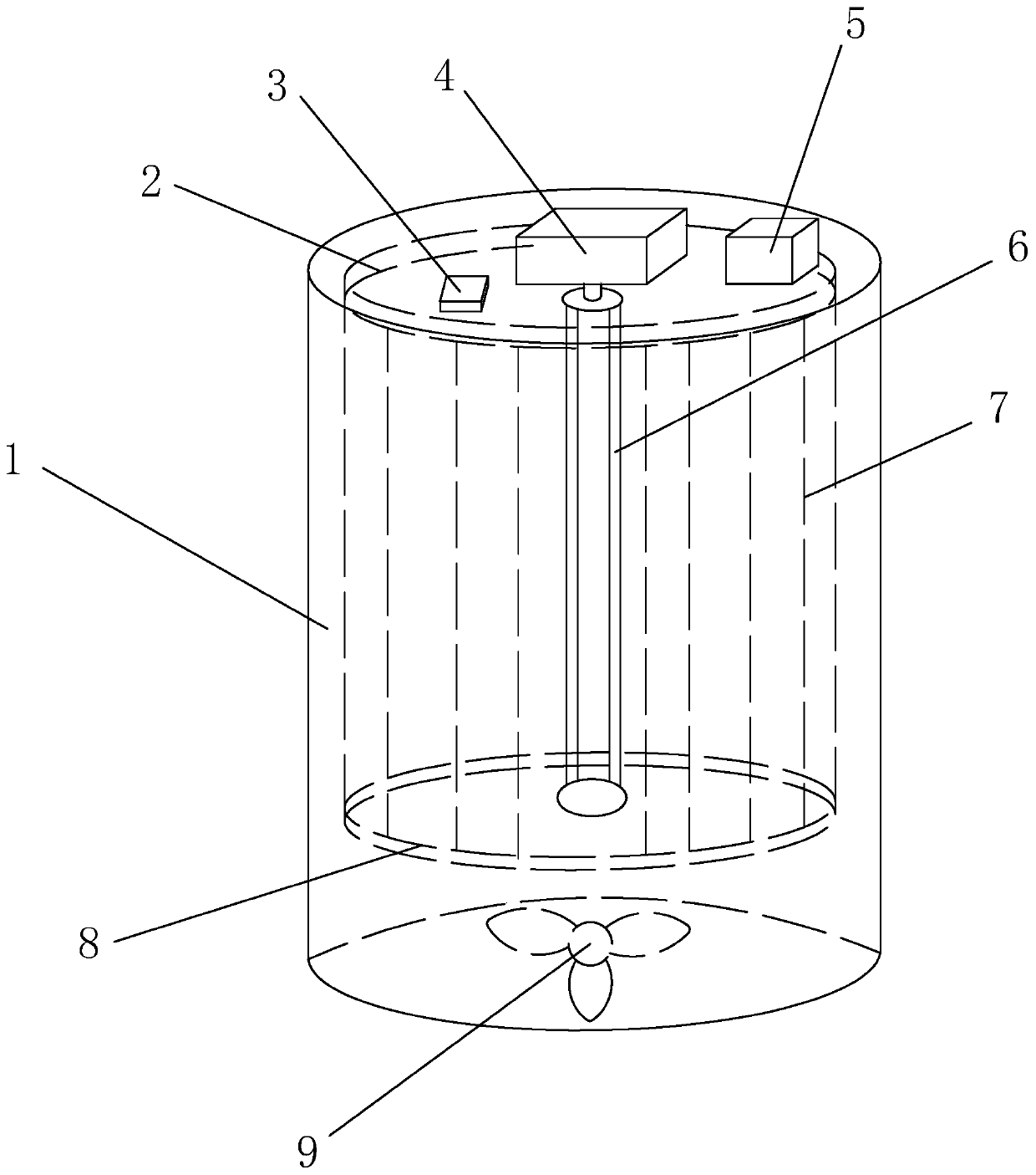
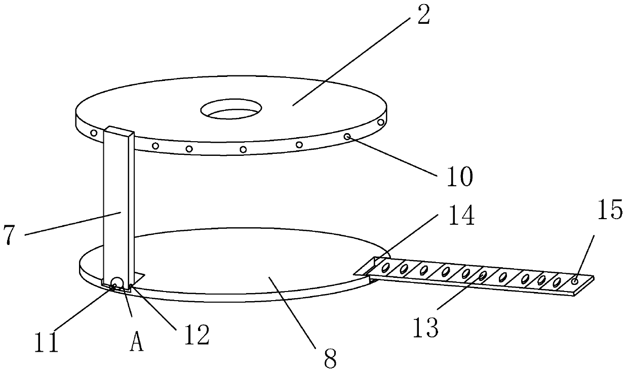
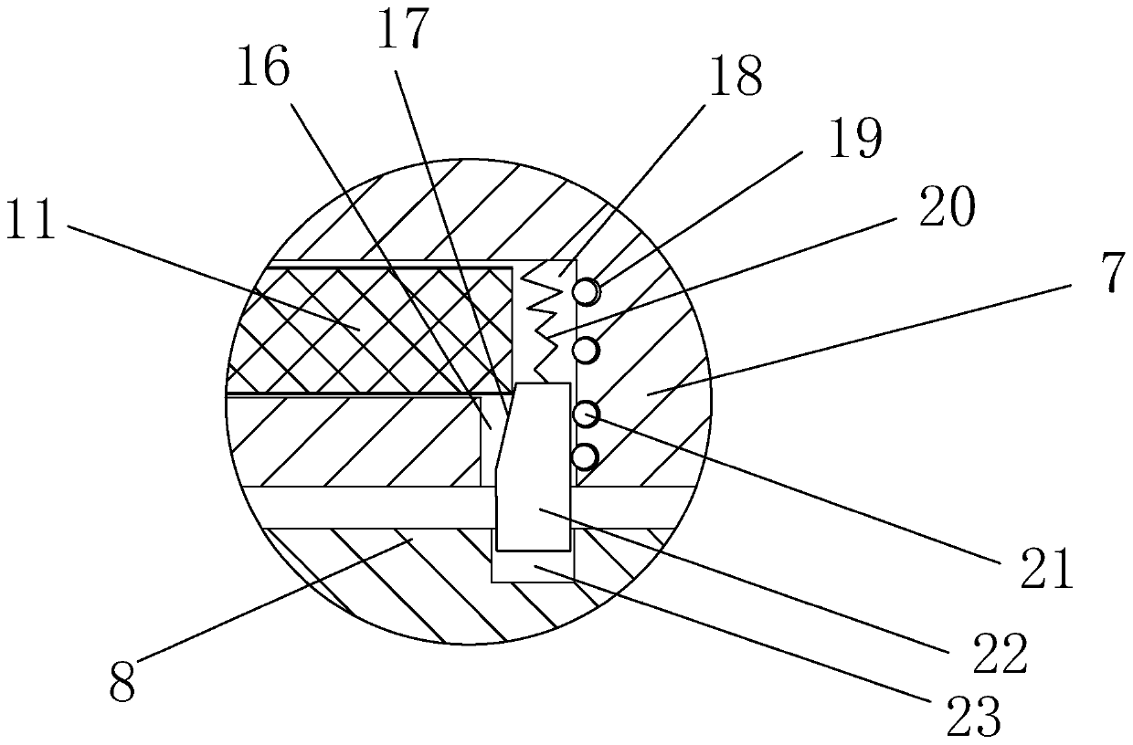
[0022] like figure 1 , 2. As shown in 3, a solar cell light attenuation machine includes a box body 1 and a control box 5, the box body 1 is provided with a rotating motor 4, and the output shaft of the rotating motor 4 is connected with a light source 6 located in the box body 1, The box body 1 is in the shape of a barrel and has a relatively regular shape, which is convenient for placing the light source 6 on the central axis of the box body 1. The rotation motor 4 can drive the light source 6 to rotate in the box body 1. The light source 6 is a xenon lamp, and the light source 6 is uniform. Installed at an angle on the central axis of the box body 1, it is used to simulate sunlight for solar cells. Both the rotating motor 4 and the light source 6 are electrically connected to the control cabinet 5, and the staff can control the rotation speed and speed of the rotating motor 4 by operating the control cabinet 5. For the power of the light source 6, a ring-shaped first brack...


PUM


Abstract

The invention relates to a test device for solar cells, in particular to a solar cell decay machine. The solar cell decay machine comprises a box body and a control cabinet; a rotating motor is arranged on the box body; an output shaft of the rotating motor is connected with a light source located in the box body; a ring-shaped first bracket around the light source is arranged at a position, closeto the rotating motor, in the box body; a second bracket matched with the first bracket is arranged at the end, close to the light source and far away from the rotating motor, in the box body; a plurality of carrier plates around the light source are arranged between the first bracket and the second bracket; one end of each carrier plate is rotatably connected with the second bracket; the other ends of the carrier plates are detachably connected with the first bracket; and a plurality of sucking disks for absorbing solar cells are arranged on the sides, close to the light source, of the carrier plates along the length directions of the carrier plates. The solar cell decay machine is uniform in light source irradiation, high in test effect reliability, large in number number of cells in asingle experiment, and high in space utilization rate.

Description

technical field [0001] The invention relates to a testing device for a solar cell, in particular to a solar cell light attenuation machine. Background technique [0002] As a renewable and clean energy source, solar cells have always been the focus of scientific research, and solar cell technology has also been developed rapidly. As we all know, the current mainstream P-type solar cells in the photovoltaic market will produce light attenuation under certain lighting conditions. A light decay test is required for solar cells. [0003] However, the light source of the equipment used for light attenuation testing on the market is usually located directly above the cell, and the cell is tiled under the light source. The position of the cell and the light source are relatively fixed, and the phenomenon of uneven light source irradiation and poor heat dissipation is common. As a result, the test effect is poor and the reliability is low. At the same time, the cells can only be ...

Claims


Application Information

Patent Timeline
Patent Type & Authority Patents(China)
IPC IPC(8): H01L21/66H01L31/18
CPCH01L22/12H01L31/1876Y02E10/50Y02P70/50
Inventor 王永楠陈健生
Owner HENGDIAN GRP DMEGC MAGNETICS CO LTD
Why Eureka
Try Eureka