
Broadband filter antenna based on microstrip-slot line form

A filter antenna and microstrip line technology, applied in the direction of antenna, slot antenna, antenna grounding device, etc., can solve the problems of lack of impedance matching, large reflection coefficient, large circuit size, etc., to facilitate processing and manufacturing, and good edge selection The effect of sex and simple structure

Inactive Publication Date: 2019-03-01
NANJING UNIV OF SCI & TECH
View PDF3 Cites 0 Cited by
  • Summary
  • Abstract
  • Description
  • Claims
  • Application Information

AI Technical Summary

Problems solved by technology

In the traditional filter antenna design, designers often focus on the design of the filter and the antenna itself, so that they cannot achieve good impedance matching after being cascaded in the system, and the circuit size is too large
[0003] In 2011, Chao-Tang Chuang and Shyh-Jong Chung published "Synthesis and Design of a New Printed Filtering Antenna" on IEEE Transaction on Antennas and Propagation. They proposed an inverted L-shaped filter antenna, which made the filter antenna smaller in size. The antenna has flat gain in the passband, and has good out-of-band rejection and edge selectivity, but the impedance matching of the entire antenna is more complicated and has a relatively large reflection coefficient
[0004] In 2016, P.F.Hu, Y.M.Pan, X.Y.Zhang, and S.Y.Zheng published "A Compact Filtering Dielectric Resonator Antenna With Wide Bandwidth and High Gain" on IEEE Transaction on Antennas and Propagation. This article introduced a rectangular medium they designed Resonator filter antenna, the size of the whole antenna is small, but the bandwidth of the antenna is small, only 20.3%
[0005] It can be seen that the existing filter antennas do not meet the requirements of simple structure and wide frequency band while achieving miniaturization.

Method used


Image

  • Broadband filter antenna based on microstrip-slot line form
  • Broadband filter antenna based on microstrip-slot line form
  • Broadband filter antenna based on microstrip-slot line form

Examples


Embodiment

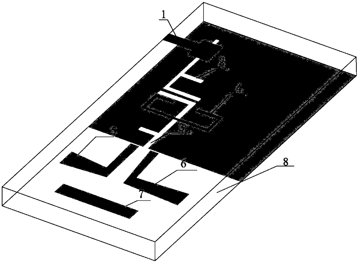
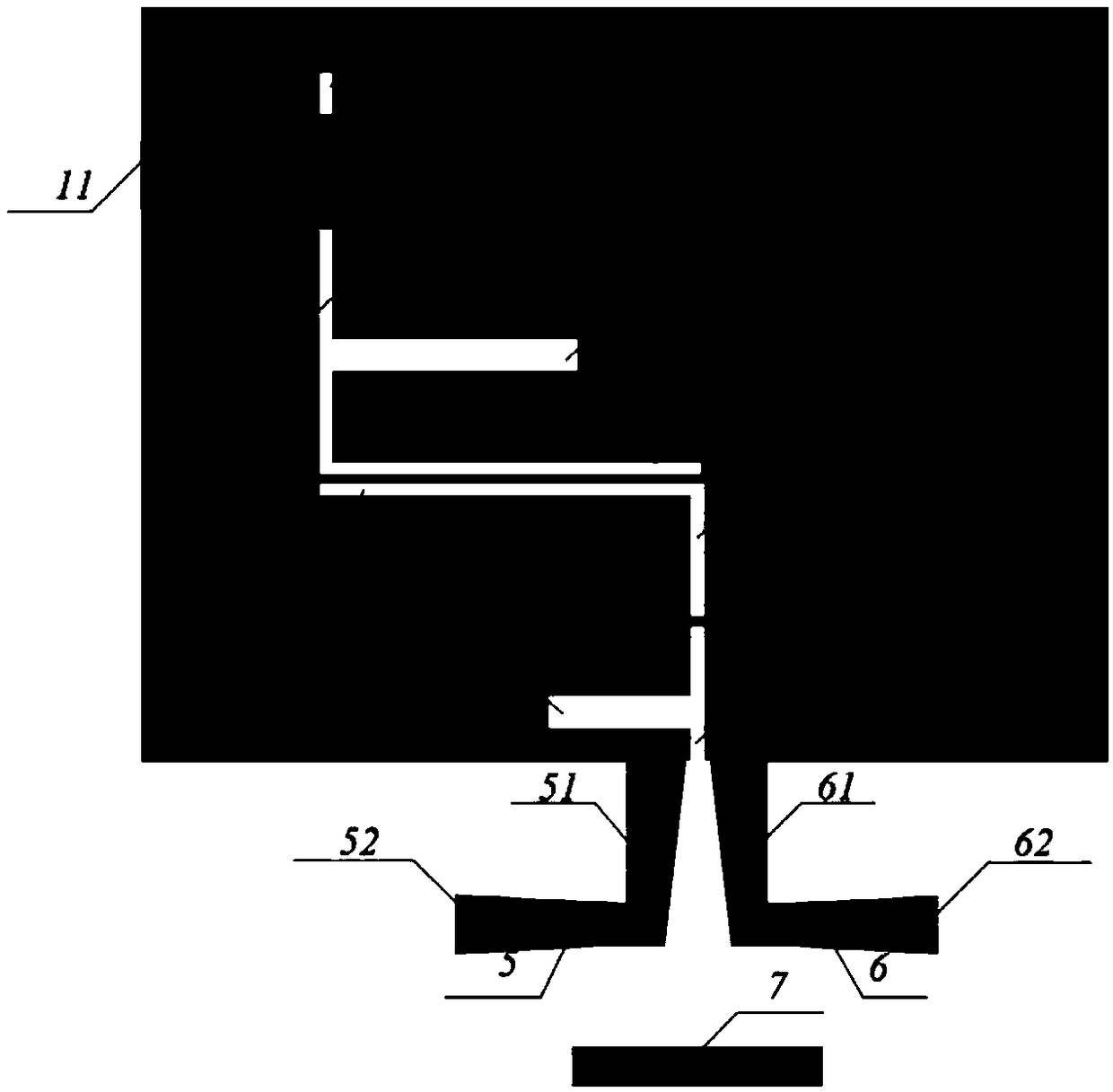
[0033] Such as figure 1 As shown, a filter antenna based on a microstrip-slot line form, including an input microstrip line 1 and an open-ended resonator 4 attached to the upper surface of a dielectric substrate 8, on the bottom ground plate of the dielectric substrate 8 The first F-shaped slot line resonator 2 and the second F-shaped slot line resonator 3 are etched, and the first radiation unit 5 and the second radiation unit 6 of the antenna connected to the metal ground plate on the lower surface of the dielectric substrate 8 are also included and director 7.

[0034] The input end microstrip line 1 includes a microstrip transmission line 11 with an input impedance of 50Ω and an open-ended low impedance line 12, and the beginning of the microstrip transmission line 11 with an input impedance of 50Ω is located on the left long side of the dielectric substrate 8, Its end is connected to the beginning of the open-circuit low-impedance line 12; the first F-shaped slot line re...


PUM


Abstract

The invention discloses a broadband filter antenna based on a microstrip-slot line form. The antenna comprises an input end microstrip line, a first F-shaped slot line resonator, a second F-shaped slot line resonator, a terminal open-circuit resonator, a first radiation unit, a second radiation unit, a director and a dielectric substrate; the first F-shaped slot line resonator and the second F-shaped slot line resonator are located on a metal grounding plate at a bottom layer of the dielectric substrate; a vertical arm of the first F-shaped slot line resonator and a vertical arm of the secondF-shaped slot line resonator are both parallel to the long side of the dielectric substrate; the input end microstrip line is located above the first F-shaped slot line resonator; an input port is arranged on the long side of the dielectric substrate; the terminal open-circuit resonator is located above the second F-shaped slot line resonator; and the input end microstrip line and the terminal open-circuit resonator are both located on a top layer of the dielectric substrate. The broadband filter antenna is realized by coupling between the microstrip line and a slot line or between slot lines,and has the advantages of small size, compact structure, small insertion loss, wide working frequency bandwidth and the like.

Description

technical field [0001] The invention belongs to the field of microwave communication passive devices, in particular to a broadband filter antenna in the form of a microstrip-slot line. Background technique [0002] With the continuous development of wireless communication, in the increasingly complex electromagnetic environment, the requirements for communication devices are getting higher and higher, and single-band communication devices are developing in the direction of miniaturization, wide frequency band, and easy processing. In recent years, the development of broadband filter antennas has also received extensive attention from scholars. In the traditional filter antenna design, designers often focus on the design of the filter and the antenna itself, so that they cannot achieve good impedance matching after being cascaded in the system, and the circuit size is too large. [0003] In 2011, Chao-Tang Chuang and Shyh-Jong Chung published "Synthesis and Design of a New P...

Claims


Application Information

Patent Timeline
Patent Type & Authority Applications(China)
IPC IPC(8): H01Q1/38H01Q1/48H01Q1/50H01Q13/10H01Q5/50
CPCH01Q1/38H01Q1/48H01Q1/50H01Q5/50H01Q13/10
Inventor 曹宗青王喆殷皓宇王建朋杨梦妮
Owner NANJING UNIV OF SCI & TECH
Learn More