
Foldable ultrathin optical imaging system

An optical imaging system and optical imaging lens technology, applied in optics, optical components, instruments, etc., can solve the problems of not being able to be used as a compensator to compensate for manufacturing tolerances, immovable image receivers, small imaging depth of field, etc., to achieve less stray light. Interference, cost saving, small size effect

Active Publication Date: 2019-03-01
TIANJIN UNIV
View PDF5 Cites 9 Cited by
  • Summary
  • Abstract
  • Description
  • Claims
  • Application Information

AI Technical Summary

Problems solved by technology

However, the front and rear surfaces of the lens need to be processed aspherically, which is difficult to process.
At the same time, the image receiver (such as CCD, etc.) located at the image plane is embedded in the lens body, and the image receiver cannot be moved. It cannot be used as a compensator to compensate for manufacturing tolerances during assembly, and it is susceptible to stray light interference.
[0009] The annular aperture folded ultra-thin optical imaging systems with various structures in the above documents and Chinese patents generally have problems such as complex structure, high processing difficulty, small imaging depth of field, and susceptibility to stray light interference.

Method used


Image

  • Foldable ultrathin optical imaging system
  • Foldable ultrathin optical imaging system
  • Foldable ultrathin optical imaging system

Examples


Embodiment Construction

[0028] The specific implementation manners of the present invention will be further described in detail below in conjunction with the accompanying drawings.

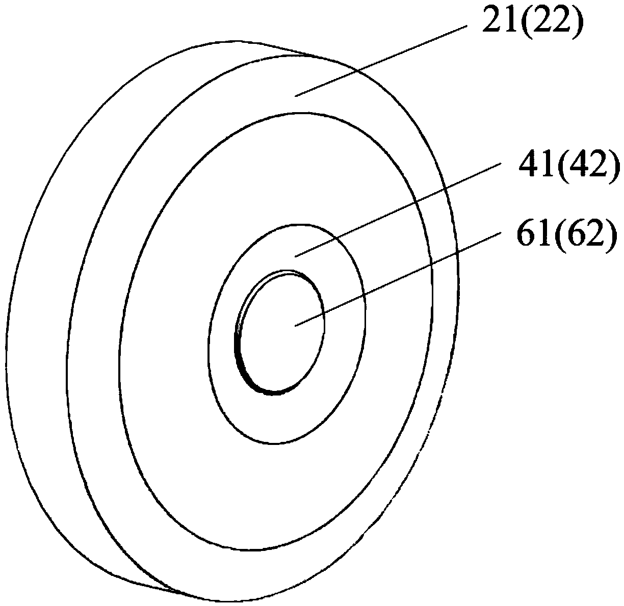
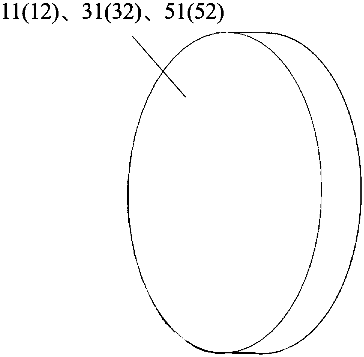
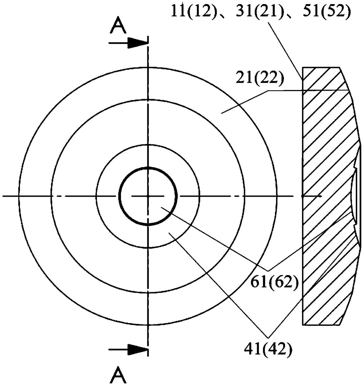
[0029] Such as Figures 1 to 4 As shown in , it is a schematic diagram of the structure of the annular aperture ultra-thin optical imaging system and a schematic diagram of the imaging principle. The light-passing plane 11-12 of the annular aperture belongs to the first and second plane mirrors 31-32 and 51-52 of the same plane as the light-passing plane 11-12 of the annular aperture; The first and second high-order aspheric mirrors 21-22, 41-42, and the high-order aspheric transmission surface 61- coaxially arranged with the first and second high-order aspheric mirrors 21-22, 41-42 62.

[0030] The substrate of the flat lens can use polymethyl methacrylate (PMMA), calcium fluoride (CaF2) and other materials as the light transmission medium, and the distance from the transmission surface to the image surface uses air a...


PUM


Abstract

The invention discloses a foldable ultrathin optical imaging system comprising an annular aperture ultrathin optical imaging lens and an imaging plane (7) and characterized in that the annular aperture ultrathin optical imaging system comprises annular light passing apertures (11)-(12) and first and second plane mirrors (31)-(32) and (51)-(52) on a front surface; and first and second high-order aspheric mirrors (21)-(22), (41)-(42) and a high-order aspheric transmission surface (61)-(62) on a rear surface. Compared with the prior art, the foldable ultrathin optical imaging system of the invention uses multiple reflection light folding technology, and has a small volume and compact structure. An image surface is kept at a distance from the rear surface of a lens. The structure is designed in such a way that the lens is less likely to be affected by external stray light. The lens has a large depth of field in an acceptable field of view, and has a wide operating range.

Description

technical field [0001] The invention relates to an optical imaging system, in particular to an annular aperture folded ultra-thin optical imaging system. Background technique [0002] With the continuous progress and development of optical manufacturing technology, it is possible to manufacture various ultra-thin micro-lenses, which are gradually designed and processed to meet the special needs of military, aerospace and commercial fields. With the development of photoelectric system application technology, the requirements for new optical systems are getting higher and higher, and various devices tend to be integrated and miniaturized in the future. This kind of ultra-thin micro-lens with compact structure and easy integration will become the future An important branch of the optical field, this kind of lens has attracted more and more attention. [0003] Traditional high-performance cameras generally adopt a lens group structure with a small radial dimension but a large a...

Claims


Application Information

Patent Timeline
IPC IPC(8): G02B17/08G02B13/00
CPCG02B13/0055G02B17/0856
Inventor 贾大功吴子祺云奋蛟朱猛张红霞刘铁根
Owner TIANJIN UNIV
Learn More