A 25g optical module

An optical module and movable block technology, applied in optics, light guides, optical components, etc., can solve the problems of reduced chip performance, increased volume heat density, failure, etc., to achieve more heat generation, improve heat dissipation efficiency, and increase heat dissipation area. Effect

Active Publication Date: 2020-06-26
HUANGSHAN OPTORAY COMM
View PDF8 Cites 0 Cited by
  • Summary
  • Abstract
  • Description
  • Claims
  • Application Information

AI Technical Summary

Problems solved by technology

The increase in the rate of the optical module is generally accompanied by the increase in power. As the power of the optical module increases, the volumetric heat density also increases, resulting in an increase in the operating temperature of the optical module. The temperature-sensitive electro-optical / photoelectric conversion components in the optical module and The performance of the chip will be greatly reduced, and even cause the entire module to fail to work or fail

Method used


Image

  • A 25g optical module
  • A 25g optical module
  • A 25g optical module

Examples


Embodiment Construction

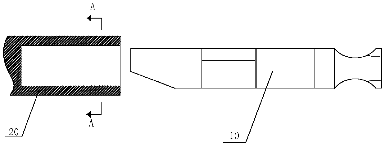
[0038] In each drawing, the optical module main body 10 is inserted into the housing 20 as the working state, and the optical module main body 10 is not inserted into the housing 20 as the non-operating state.

[0039] Such as figure 1 As shown, a 25G optical module includes an optical module main body 10 and an opening at one end, and a housing 20 for inserting the optical module main body 10. The optical module main body 10 can be socketed inside the housing 20 or not. , placed alone.

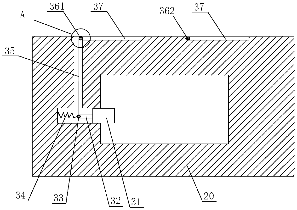
[0040] Such as Figure 2-5 As shown, the housing 20 includes a base with a cavity inside, and the cavity can allow the optical module main body 10 to enter and exit. A heat dissipation part is arranged above the base. The base part and the heat dissipation part are actually a whole, but are divided into two parts for the convenience of description.

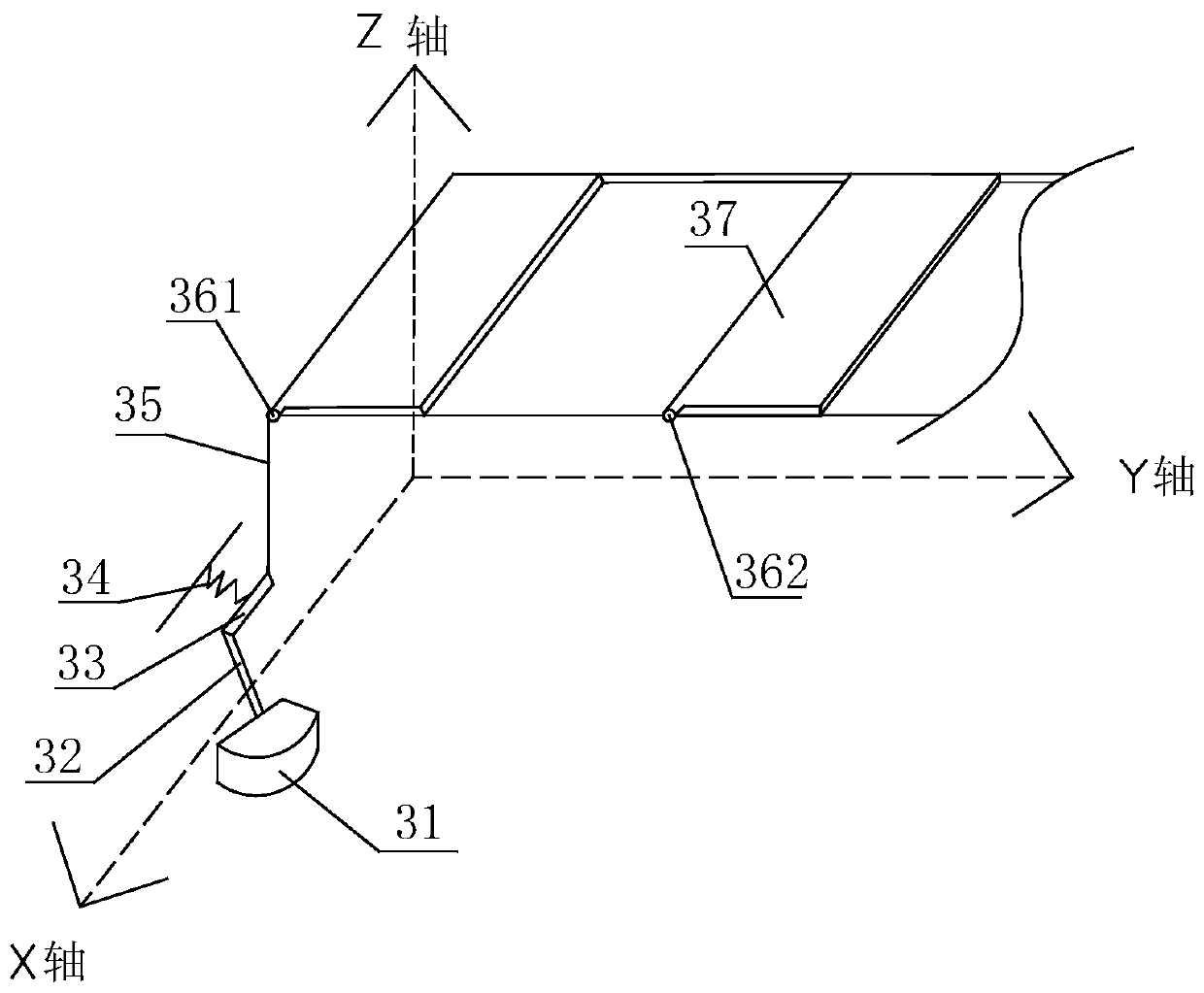
[0041] An installation channel is provided on at least one side wall near the opening of the base. A movable block 31 is housed inside the ...


PUM


Abstract

The invention belongs to the field of electronic communication devices, and relates to a 25G optical module. According to the specific technical schemes of the invention, the 25G optical module includes an optical module main body and a housing; the housing includes a base portion; a heat dissipation portion is disposed on the base portion; a mounting channel is formed in at least one side wall adjacent to the opening of the base portion; a movable block is arranged in the mounting channel; the outer end of the movable block is a free end; and an elastic component is arranged between the innerend of the movable block and the bottom of the mounting channel. When the optical module body is separated from the housing, the free end of the movable block extends into a cavity; the inner end ofthe movable block is connected with a tension rope; one end of the tension rope extends into the heat dissipating portion and is fixedly connected with the rod surface of a first movable rod, whereinthe rod surface of the first movable rod is adjacent to the end surface of the first movable rod; the first movable rod is hinged to the upper surface of the heat dissipating portion; the first movable rod is fixedly connected with fins; fin grooves are correspondingly formed in the heat dissipating portion; and the tension rope is connected with the first movable rod in such a manner that an angle between the tangent of the fixed joint of the tension rope and the first movable rod on the circular cross section of the first movable rod and the fins ranges from 90 to 180 degrees. The heat dissipation structure of the 25G optical module of the invention is simple and reasonable, and can effectively meet the daily heat dissipation requirements of the optical module.

Description

technical field [0001] The invention belongs to the field of electronic communication equipment, and in particular relates to a 25G optical module. Background technique [0002] As the bandwidth in the field of optical communication continues to increase, the bandwidth of optical modules has also been upgraded. In response to the market's demand for high-bandwidth and high-speed data transmission, module design is increasingly developing in the direction of miniaturization and high density. The increase in the rate of the optical module is generally accompanied by the increase in power. As the power of the optical module increases, the volumetric heat density also increases, resulting in an increase in the operating temperature of the optical module. The temperature-sensitive electro-optical / photoelectric conversion components in the optical module and The performance of the chip will be greatly reduced, and even cause the entire module to fail to work or fail. Therefore, ...

Claims


Application Information

Patent Timeline
Patent Type & Authority Patents(China)
IPC IPC(8): G02B6/42H05K7/20
CPCG02B6/4256G02B6/4269H05K7/20418H05K7/20427
Inventor 汪洋朱汝俊吴海峰
Owner HUANGSHAN OPTORAY COMM
Why Eureka
Try Eureka