
Manufacturing method of trench Schottky front silver surface metal structure

A surface metal and manufacturing method technology, applied in semiconductor/solid-state device manufacturing, electrical components, circuits, etc., can solve problems such as difficult processing, prone to inverted triangles, and unstable etched morphology, reducing the processing technology. Instability, optimization of inter-film stress, avoidance of apparent anomalies

Active Publication Date: 2019-02-26
TIANJIN HUANXIN TECH DEV
View PDF11 Cites 0 Cited by
  • Summary
  • Abstract
  • Description
  • Claims
  • Application Information

AI Technical Summary

Problems solved by technology

At present, the following methods are mainly used to manufacture the grooved Schottky front silver surface metal structure: first, use the lift off process to perform photolithography three times, and then evaporate or sputter metal on the surface of the photoresist, and use the film to remove the metal structure. The metal on the photoresist is peeled off by the film method, the process cost is high, a special photoresist is required, and there are problems such as metal residue when the film is peeled off; the second method is to perform a photoetching on the metal surface , and then etch the metal, the etched morphology is unstable, prone to over-etching and metal residues
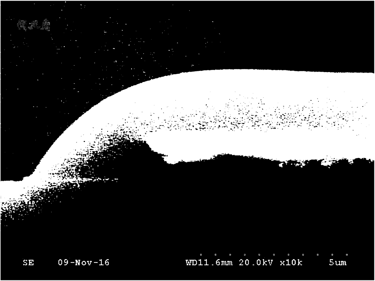
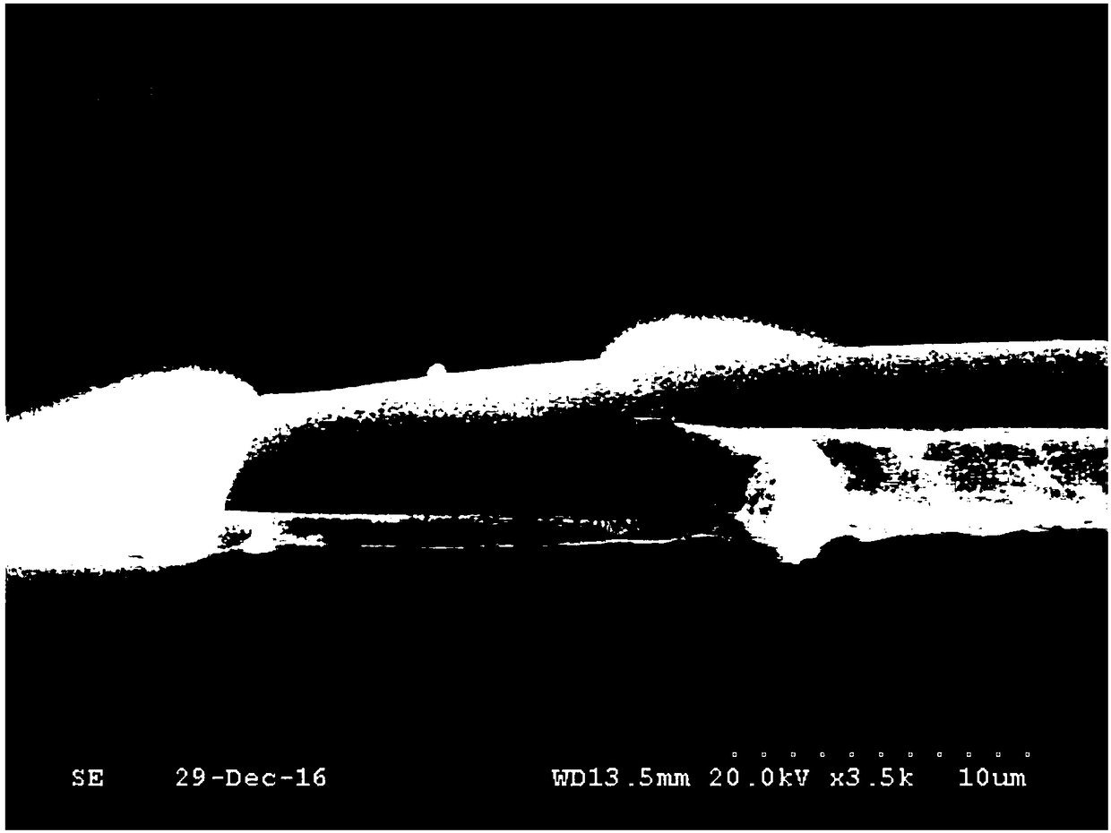
[0004] The following problems occurred in the actual manufacturing of the grooved Schottky front silver surface metal structure: 1. Due to the existence of the grooves and the stress between the metal films, the warpage of the wafer is too large and the processing is difficult; 2. , The composite metal film is difficult to corrode, prone to over-etching and metal residues, and the corrosion morphology is as follows figure 1 The inverted triangle phenomenon is easy to appear, which directly affects the adhesion between metal films and product reliability

Method used


Image

  • Manufacturing method of trench Schottky front silver surface metal structure
  • Manufacturing method of trench Schottky front silver surface metal structure
  • Manufacturing method of trench Schottky front silver surface metal structure

Examples


Embodiment

[0025] Firstly, the trench Schottky product sheet to be used as a potential barrier is cleaned before the barrier: the silicon wafer is cleaned with a cleaning solution with a volume ratio of HF:H2O of 20:1, and the cleaning time is 20 minutes. The surface of the chip is clean and will not affect the subsequent steps, so that the obtained barrier structure parameters are stable;

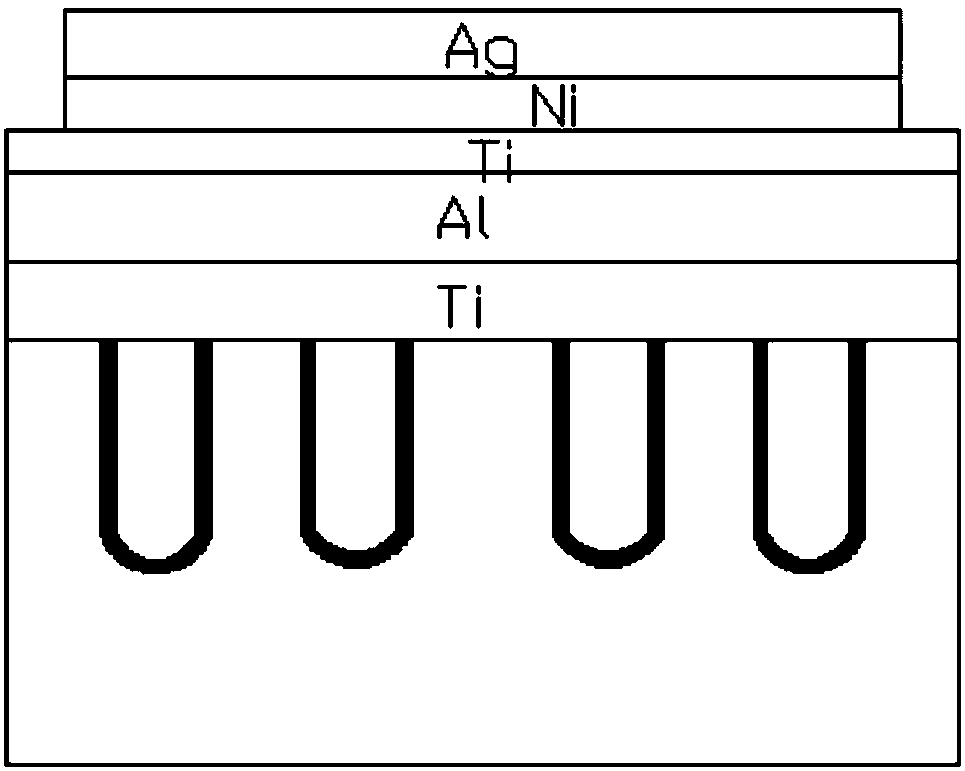
[0026] The thickness of the evaporated Ti barrier is Form a silicon wafer-Ti barrier structure. The Ti metal layer of this thickness is stable and the barrier is not prone to defects; It is an alloy of barrier metals, thereby forming a Schottky barrier and releasing stress at the same time;

[0027] The aluminum metal is then evaporated to a thickness of Form a silicon wafer-Ti barrier-aluminum metal layer structure, followed by annealing, the annealing temperature is 300-600°C, and the annealing time is 0.5-2h; Forming a silicon wafer-Ti barrier-aluminum metal layer-TiNiAg metal layer structur...


PUM


Abstract

The present invention discloses a manufacturing method of a trench Schottky front silver surface metal structure. The method comprises the following steps of: a. forming a barrier metal layer on a silicon wafer to form a silicon wafer-barrier metal structure; b. performing first heat treatment for the silicon wafer-barrier metal structure; c. forming a first metal layer on the barrier metal layerto form a silicon wafer-barrier metal-first metal layer structure; d. performing second heat treatment of the silicon wafer-barrier metal-first metal layer structure; and e. depositing a second metallayer on the first metal layer. The manufacturing method of a trench Schottky front silver surface metal structure employs an appropriate metal thin film thickness and an alloy condition, performs metal alloy at the front of the titanium nickel silver to avoid abnormal appearance of products, and employs a method for twice photoetching and twice corrosion of multi-layer metal thin films to allow the corrosion morphology of the metal to be stable, facilitate improvement of the product reliability; and moreover, the process provided by the invention is compatible with a routine process in the prior art with no need for special devices and introduction of a new photoresist.

Description

technical field [0001] The invention relates to a front silver surface metal technology, in particular to a method for manufacturing a grooved Schottky front silver surface metal structure. Background technique [0002] Schottky barrier diodes have been used in power supply applications for decades as rectifying devices. Compared with PN junction diodes, Schottky barrier diodes have the advantages of low forward turn-on voltage and fast switching speed, which makes them very suitable for switching power supplies and high-frequency applications. [0003] Schottky barrier diodes are manufactured using the principle of a metal-semiconductor junction formed in contact between a metal and a semiconductor. Trench Schottky adopts the principle that the trench structure produces a depletion layer to pinch off the conductive channel, and its high-frequency characteristics and electrical performance are significantly better than those of the planar Schottky. At present, the followin...

Claims


Application Information

Patent Timeline
Patent Type & Authority Applications(China)
IPC IPC(8): H01L21/324H01L21/321H01L21/329H01L21/285H01L29/47
CPCH01L21/28537H01L21/2855H01L21/321H01L21/324H01L29/47H01L29/66143
Inventor 刘晓芳王彦君孙晨光徐长坡王万礼张新玲刘丽媛董子旭杜宏强刘闯张晋英刘文彬乔智印小松张娇
Owner TIANJIN HUANXIN TECH DEV
Learn More