
Device for controlling welding stress deformation along with soldering impact, revolving and extrusion pressing

A technology that follows welding impact and welding stress. It is applied in the direction of auxiliary equipment, welding equipment, auxiliary welding equipment, etc. It can solve the problems of poor working environment, high noise, and the distance between wheel and gun that cannot meet the theoretical ideal value, etc., and achieve low cost and low noise. The effect of small and small residual deformation

Inactive Publication Date: 2008-03-12
HARBIN INST OF TECH
View PDF1 Cites 29 Cited by
  • Summary
  • Abstract
  • Description
  • Claims
  • Application Information

AI Technical Summary

Problems solved by technology

[0003] Aiming at the problem that the device for controlling welding stress and deformation with welding impact rolling is noisy, the working environment is poor, and affected by the impact rolling wheel and the size of the welding torch, the distance between the wheel and the torch cannot meet the theoretical ideal value. The present invention provides a A device for controlling welding stress and deformation by rotating and extruding with welding impact

Method used


Image

  • Device for controlling welding stress deformation along with soldering impact, revolving and extrusion pressing
  • Device for controlling welding stress deformation along with soldering impact, revolving and extrusion pressing

Examples


specific Embodiment approach 2

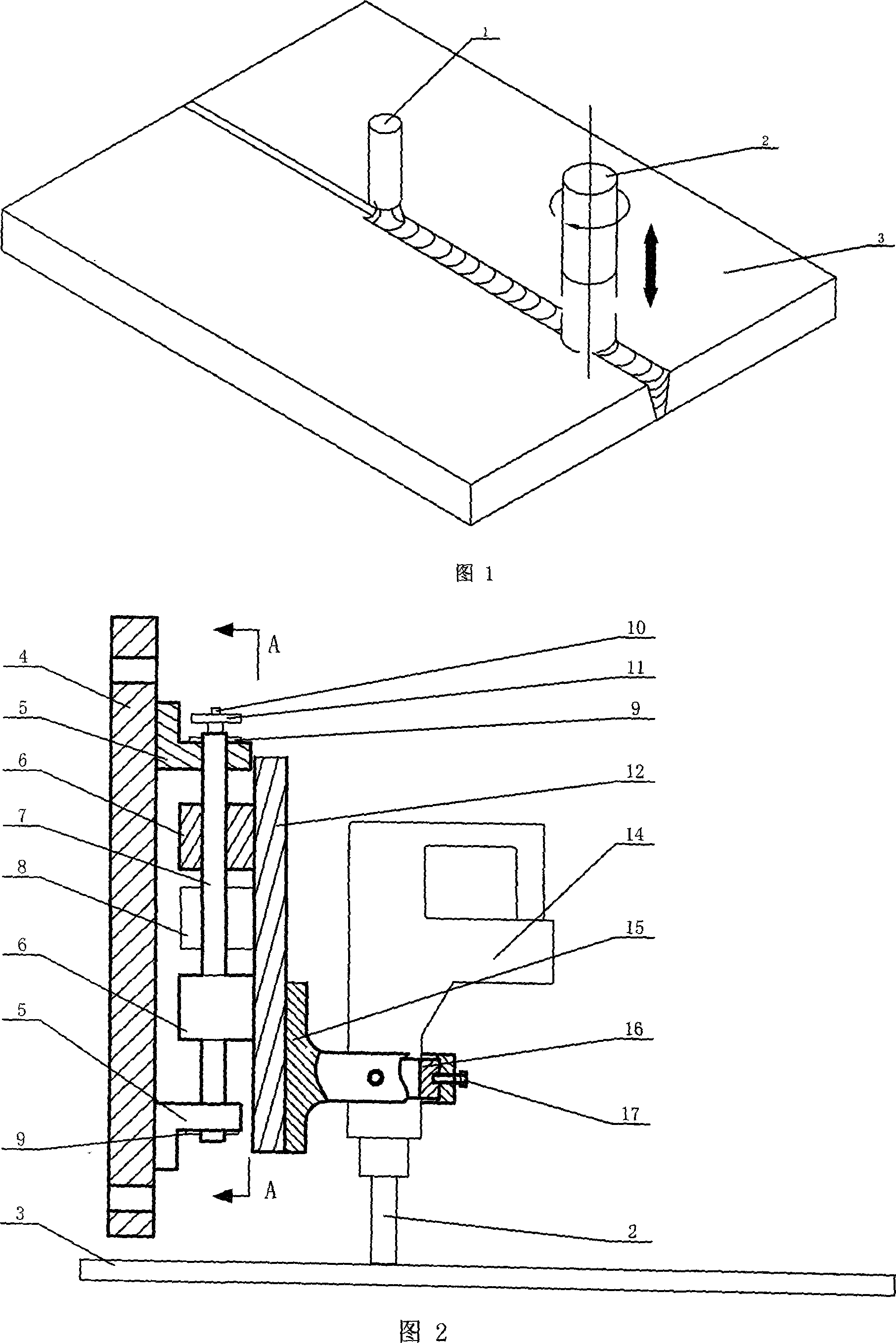
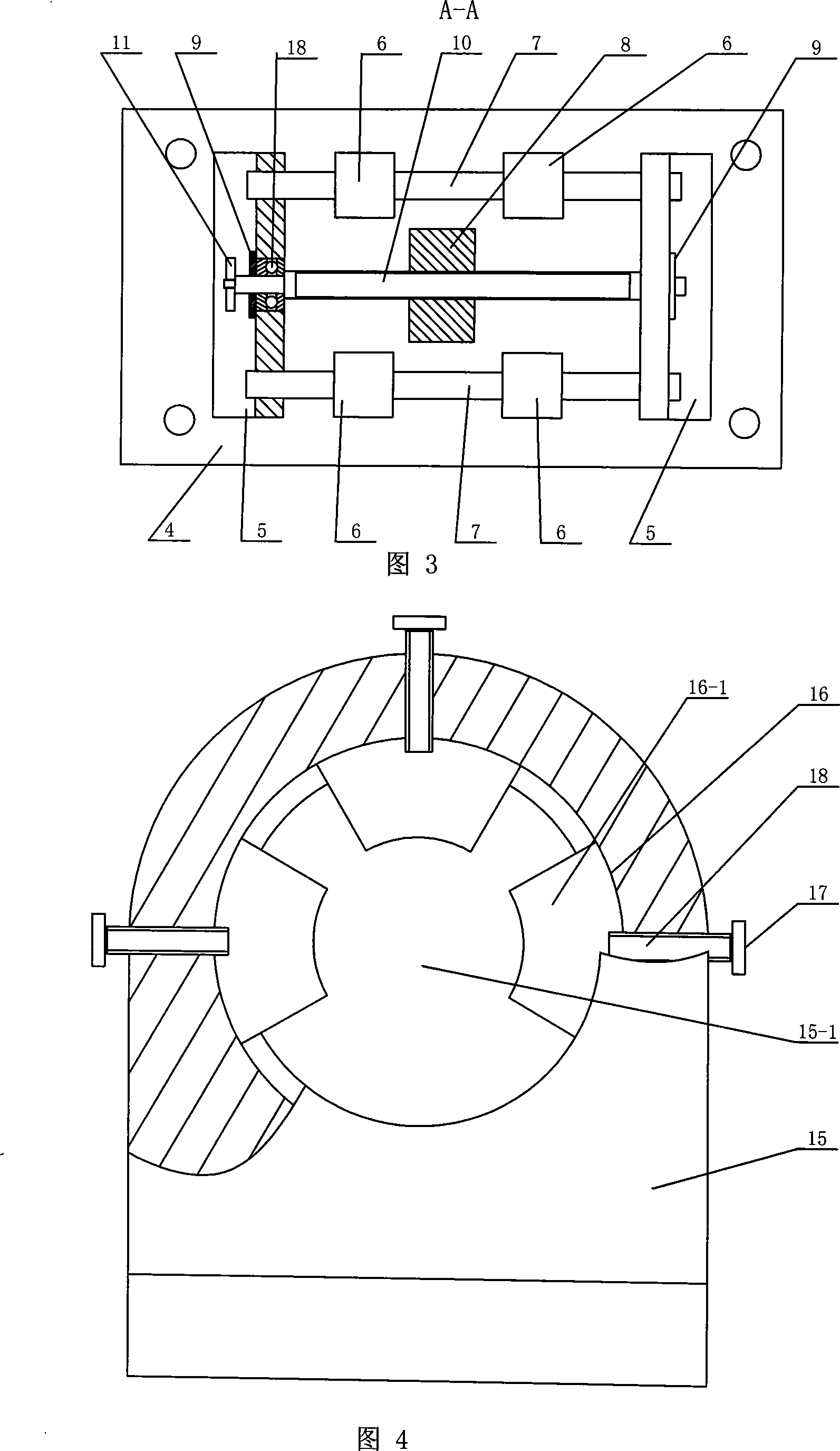
[0007] Specific Embodiment 2: This embodiment is described in conjunction with FIG. 4 . In this embodiment, the clamping block 16 is composed of three clamping block monomers 16-1, and the three clamping block monomers 16-1 are fixed on the channel of the second support 15. In the hole 15-1 and evenly distributed along the circumference of the hole wall, the outer end surface of the block unit 16-1 is tangent to the inner hole wall of the through hole 15-1, and the inner end surface of the block unit 16-1 is in contact with the electric hammer 14 Tangent to the outer wall. Such setting is for positioning the electric hammer 14 . Other compositions and connections are the same as those in the first embodiment.

[0008] Specific embodiment three: This embodiment is described in conjunction with FIG. 4. In this embodiment, the adjustment member 17 is a set screw 18, and the three clamping block monomers 16-1 are fixed to the second support 15 through three set screws 18, respect...


PUM


Abstract

A weld with trailing rotation extruding to control residual stresses deformation device relates to a device for controlling the residual stress deformation of a thin-walled metal. The weld with trailing impact rolling to control residual stresses deformation device has the disadvantages that the device has a loud noise during operation and a bad working environment and that the device is easily influenced by the impact rolling wheel and the size of the welding torch and that the distance between the wheel and the torch can not satisfy the theoretical ideal value. The upper end of a compression rod (2) is inserted into the part of the head of an electric hammer (14), which is fastened on a No.2 support (15). A pair of sliders (6) which mate with two guide rails (7) and a nut (8) which mates with an elevating screw (10) are fixed on the other side of the bottom plate (12). Both ends of the guide rail (7) are fixedly arranged on a support (5). The two guide rails (7) are parallel with the elevating screw (10), both ends of which are equipped with bearings (13). The support (5) is fixed on a base (12). The present invention with an adjustable frequency impact force can effectively prevent a welding hot cracking as well as control a straight weld and an enclosed circumferential weld.

Description

technical field [0001] The invention relates to a device for controlling welding stress deformation of thin-walled metals. Background technique [0002] Welding of high-strength thin-walled materials, the stress deformation is large, and thermal cracks are prone to occur. Correction and heat treatment are required after welding, which increases production costs, affects product quality, and even produces waste products. In order to solve the above problems, a variety of methods such as rolling with welding, static and dynamic temperature difference stretching and hammering with welding have been proposed at home and abroad, and the devices for realizing these methods, but they generally have low production efficiency, high cost, and poor working environment. and other shortcomings. The rolling method with welding has disadvantages such as large size of the impact rolling wheel and easy occurrence of arcing due to interference with the welding torch, so it is difficult to be...

Claims


Application Information

Patent Timeline
IPC IPC(8): B23K37/00C21D9/50C21D7/00
CPCY02P10/20
Inventor 方洪渊杨建国刘雪松翁路露李军
Owner HARBIN INST OF TECH
Learn More