High rigidity and light space camera lens cylinder and test method for vibration resistance stability thereof

A space camera, high stiffness technology, applied in the field of support between the primary mirror and secondary mirror of space high-resolution cameras, high stiffness and lightweight space camera lens barrels, can solve the problems of poor stability of resin-based composite materials, and reach the market Broad application prospects, improved stability and strong versatility

Active Publication Date: 2019-02-26
BEIJING RES INST OF SPATIAL MECHANICAL & ELECTRICAL TECH
View PDF6 Cites 5 Cited by
  • Summary
  • Abstract
  • Description
  • Claims
  • Application Information

AI Technical Summary

Problems solved by technology

[0005] The technical problem solved by the present invention is: to overcome the deficiencies of the prior art, the present invention provides a high-rigidity and light-weight space camera lens barrel, which optimizes the The overall structure of the lens barrel makes up for the defects of the traditional metal support structure that is too heavy and has a large expansion coefficient; through the design of the anti-vibration stability test method of the lens barrel structure, the overall stability of the lens barrel is ensured, and the traditional problem is solved. The problem of poor stability of resin matrix composites

Method used


Image

  • High rigidity and light space camera lens cylinder and test method for vibration resistance stability thereof
  • High rigidity and light space camera lens cylinder and test method for vibration resistance stability thereof
  • High rigidity and light space camera lens cylinder and test method for vibration resistance stability thereof

Examples


Embodiment Construction

[0029] In order to make the solution of the present invention clearer, the present invention will be further described below in conjunction with the accompanying drawings and specific embodiments:

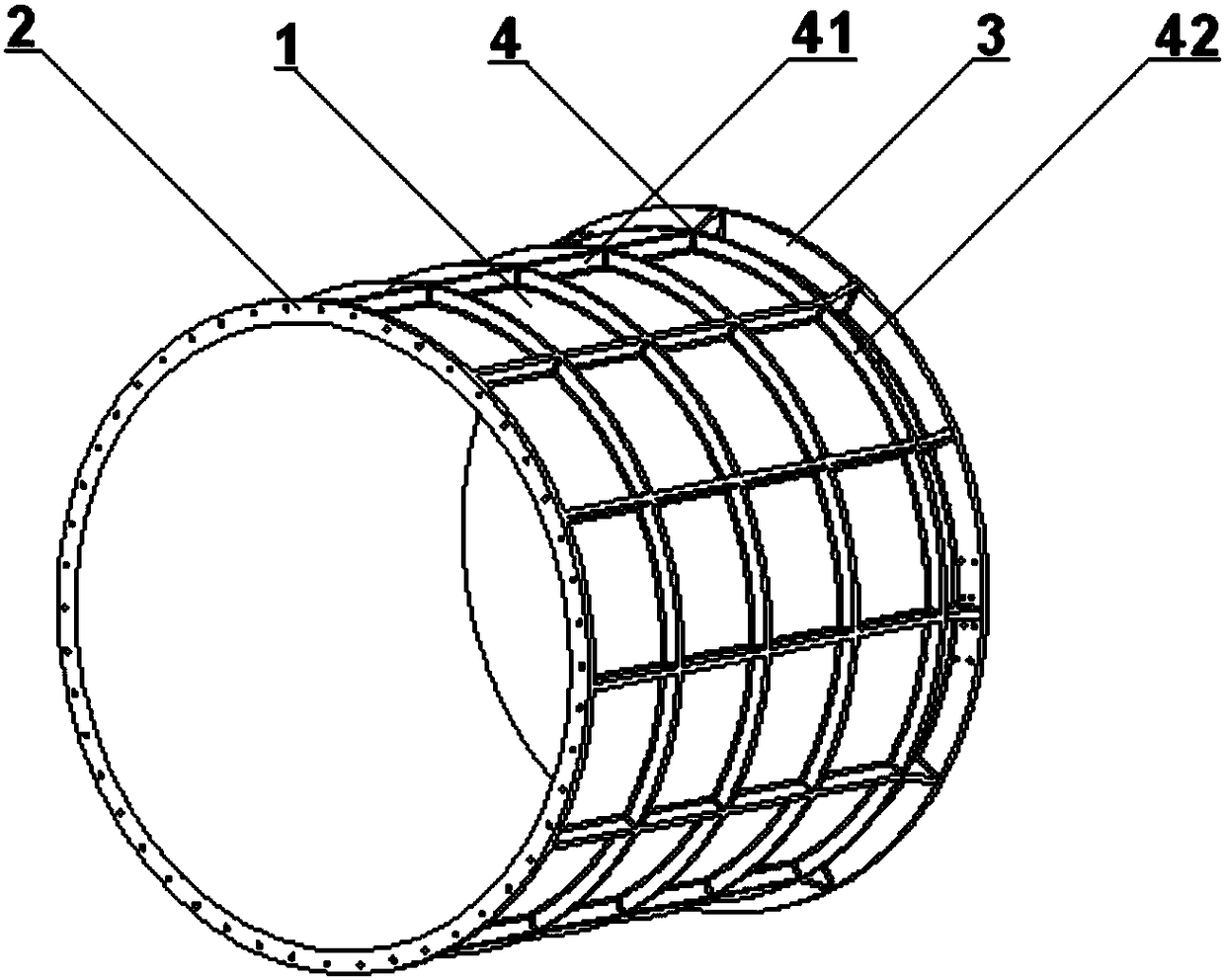
[0030] Such as figure 1 As shown, a high-rigidity light-weight space camera lens barrel includes a barrel body 1, a primary mirror flange 2, a secondary mirror flange 3 and a reinforcing rib 4; the barrel body 1 is a hollow cylinder, and one end of the barrel body 1 is provided with a The main mirror flange 2 of the main mirror of the space camera and the other end of the cylinder body 1 are provided with a secondary mirror flange 3 for connecting the secondary mirror of the space camera, and the outside of the cylinder body 1 is provided with reinforcing ribs 4 for reinforcing the structure. The primary mirror flange 2, the secondary mirror flange 3 and the rib 4 are integrally formed by three-dimensional braiding of silicon carbide.

[0031] Preferably, the ratio of the inner di...


PUM


Abstract

The invention discloses a high rigidity and light space camera lens cylinder and a test method for vibration resistance stability thereof. The cylinder comprises a cylinder body, a main mirror flange,a secondary mirror flange and a reinforcing rib. The cylinder body is a hollow cylinder. One end of the cylinder body is provided with a main mirror flange for connecting a space camera main mirror,and the other end of the cylinder is provided with the secondary mirror flange for connecting the space camera secondary mirror. The outer side of the cylinder body is provided with a reinforcing ribfor reinforcing the structure. The cylinder body, the main mirror flange, the secondary mirror flange and the rib are integrally formed by three-dimensional braiding silicon carbide. According to theinvention, the overall structure of the lens cylinder is optimized by integrally forming the cylinder body, the flanges and the reinforcing rib through using the three-dimensional braiding of siliconcarbide materials, and the defect that the traditional metal support structure is too heavy and has a large self-expansion coefficient is overcome; by designing the vibration resistance stability testmethod of the lens cylinder structure, the stability of the entire lens cylinder is ensured; and the problem of quite poor stability of the conventional resin-based composite material is solved.

Description

technical field [0001] The invention relates to a high-rigidity and lightweight space camera lens barrel, which is especially suitable for supporting between a primary mirror and a secondary mirror of a high-resolution space camera, and belongs to the technical field of internal support structures of space cameras. Background technique [0002] Aerospace high-resolution cameras mostly use a cylinder as a supporting structure. The change in the distance between optical parts caused by temperature will be determined by the linear expansion coefficient of the cylinder, and the change in the distance between optical parts will cause extreme differences in focal length and image plane position. Large changes, so the thermal stability of the optical spacing must be strictly controlled. [0003] General materials such as aluminum alloy or titanium alloy, due to the large linear expansion coefficient of the material itself, are mostly used as small structural size lens barrels. The...

Claims


Application Information

Patent Timeline
Patent Type & Authority Applications(China)
IPC IPC(8): G03B17/02G01M7/02G01M11/08
CPCG03B17/02G01M7/00G01M11/08
Inventor 罗世魁李明曹东晶高超唐璐罗廷云史姣红潘宁贤岳聪张志飞董绍明丁玉生曹英斌刘荣军
Owner BEIJING RES INST OF SPATIAL MECHANICAL & ELECTRICAL TECH
Why Eureka
Try Eureka