Electric pulse auxiliary spinning forming machine tool

A technology of spinning forming and electric pulse, which is applied in the direction of forming tools, metal processing equipment, manufacturing tools, etc., can solve the problems of the temperature rise of the rotary wheel bearing, the inability to fully utilize the material, and the increase of contact resistance, so as to reduce energy loss, The effect of avoiding the reduction of the current utilization rate and improving the spinning performance

Active Publication Date: 2019-02-22
SOUTH CHINA UNIV OF TECH
View PDF15 Cites 5 Cited by
  • Summary
  • Abstract
  • Description
  • Claims
  • Application Information

AI Technical Summary

Problems solved by technology

[0003] The characteristic of spinning forming is that the instantaneous deformation zone is very small, and the deformation zone is always located near the contact point between the spinning wheel and the blank. Therefore, when the spinning forming process uses electric pulse-assisted forming technology, if the deformation zone cannot be placed in a high-energy pulse current The area with the highest density will seriously affect the performance of the electrotropic effect
In the current electroplastic spinning machine tools, the current loading method is either that the two poles of the power supply are respectively loaded on the blank and the tail ejector rod, and the closed loop circuit formed by the power supply cannot make the point contact area between the rotary wheel and the blank a strong electroplastic area. Most of them use the electrothermal effect instead of the electroplastic effect for spinning forming, so they cannot fully play the role of improving the plasticity of the material; The arms are usually lubricated by various greases, and its insulating effect will inevitably cause the current channel to be narrowed and the local contact resistance will increase, resulting in the temperature of the internal bearing of the rotary wheel rising and the life shortened sharply, that is, the electrothermal effect is not applied to the billet but Wrongly screwed on the bearing of the roller

Method used


Image

  • Electric pulse auxiliary spinning forming machine tool
  • Electric pulse auxiliary spinning forming machine tool
  • Electric pulse auxiliary spinning forming machine tool

Examples


Embodiment Construction

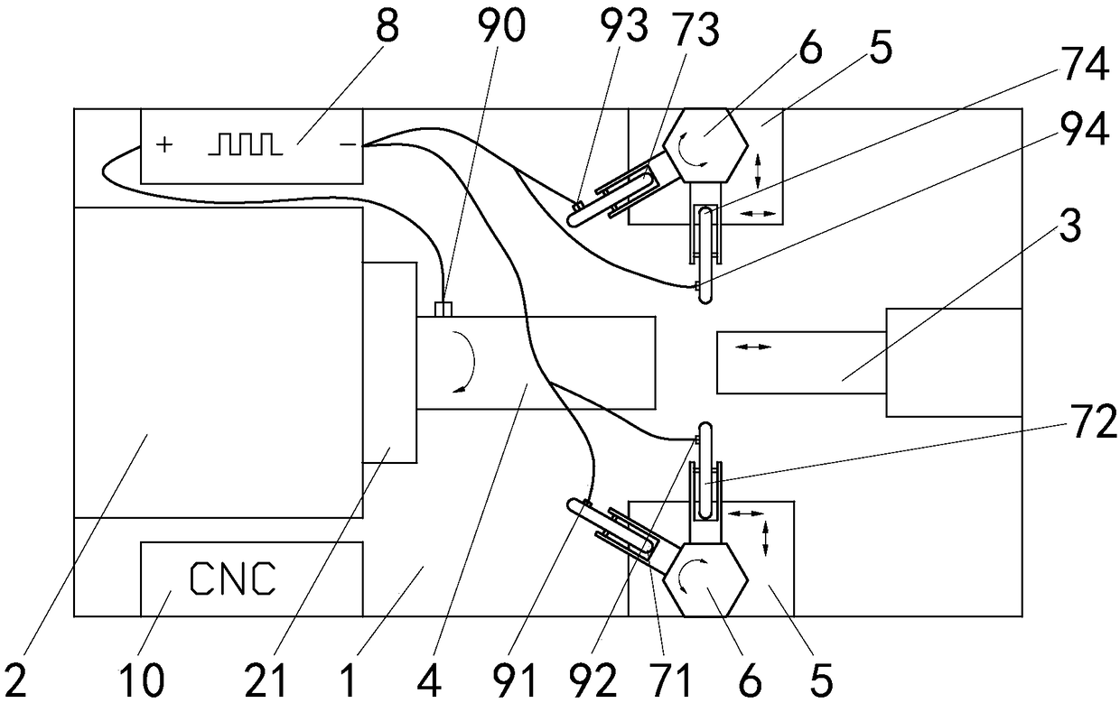
[0020] refer to figure 1 and Figure 5 , the present invention is an electric pulse assisted spinning forming machine tool, which includes a machine tool body 1, a high-energy pulse power supply 8 and a control unit 10, and the two ends of the machine tool body 1 are respectively fixed with a bedside box 2 and a tail top 3, and the bedside box Mandrel 4 is installed on the main shaft 21 of 2, and mandrel 4 rotates together with main shaft 21, and the center line of main shaft 21, mandrel 4 and tail crown 3 coincides, and the both sides of mandrel 4 and tail mandrel 3 are respectively provided with a movable On the mobile platform 5 that moves on the machine tool body 1, rotatable wheel seats 6 are installed on the two mobile platforms 5, and each wheel seat 6 is equipped with a wheel 7. The positive pole of the high-energy pulse power supply 8 passes through the brush 9 is connected to the mandrel 4, the negative electrode is connected to each rotary wheel 7 through the brush...


PUM


Abstract

The invention discloses an electric pulse auxiliary spinning forming machine tool. A machine tool body, a high energy pulse power source and a control unit are included. A headstock and a tail ejectorare fixed to the two ends of the machine tool body correspondingly. A main shaft of the headstock is provided with a core die. The center line of the main shaft, the center line of the core die and the center line of the tail ejector are in coincidence. Each of the two sides of the core die and the two sides of the tail ejector is provided with a movable platform capable of moving on the machinetool body. Each movable platform is provided with a rotary rotation wheel base. Rotation wheels are arranged on the rotation wheel bases. The positive electrode and the negative electrode of the highenergy pulse power source are connected with the core die and the rotation wheels through electric brushes. The contact faces of the electric brushes and the rotation wheels are in an opening circularring shape. The control unit conducts CNC over the motion of various components on the machine tool body. The high energy pulse current is applied between the core die and the rotation wheels, accordingly, the shortest current path is formed among the core die, a workpiece and the rotation wheels, the current utilization rate is increased, the spinning deformation area can be constantly limited at the part where the current density is the largest, and the electroplastic efficiency is improved to the maximum degree.

Description

technical field [0001] The invention relates to the technical field of special processing of mechanical engineering, in particular to an electric pulse assisted spinning forming machine tool. Background technique [0002] For spinning forming of difficult-to-deform metals, it is often necessary to take some technological measures to improve the plasticity of the metal and reduce the deformation resistance, such as heating the blank with a heating furnace and then putting it on the machine tool for spinning, or changing the heating method to direct Flame or electric induction heating is used on the machine tool. In recent years, an electroplastic method has been developed: a high-energy pulse current is passed through a metal material to generate a large number of directional drift free electrons, and the drift electron group frequently directionally hits the dislocation, generating an electronic wind force similar to the applied stress on the dislocation segment, promoting ...

Claims


Application Information

Patent Timeline
Patent Type & Authority Applications(China)
IPC IPC(8): B21D22/16B21D37/16
CPCB21D22/16B21D37/16
Inventor 夏琴香程秀全肖刚锋程思竹徐腾
Owner SOUTH CHINA UNIV OF TECH
Why Eureka
Try Eureka