
High-coverage automatic radio frequency index test device

An automatic test device and automatic test technology, applied in electrical components, wireless communication, network planning, etc., can solve the problems of difficult full coverage of automatic testing, cumbersome operation process, and many test items, etc., to achieve rapid automatic testing, ensuring The effect of rapid verification and reduced cost investment

Inactive Publication Date: 2019-02-01
10TH RES INST OF CETC
View PDF5 Cites 13 Cited by
  • Summary
  • Abstract
  • Description
  • Claims
  • Application Information

AI Technical Summary

Problems solved by technology

[0005] The present invention is aimed at the problems of many radio frequency equipment test items, long test time, cumbersome operation process and the current automatic test system of radio frequency microwave circuits with strong customization and poor versatility, and it is difficult to realize full-coverage automatic test of module types and index tests , to provide a full-coverage automated test that can realize multiple types of radio frequency modules and various performance indicators, and is suitable for the whole process application of radio frequency module development, which can reduce the cost of test and measurement equipment and improve the test accuracy and test efficiency of radio frequency modules High-coverage RF index automatic test device based on modular design

Method used


Image

  • High-coverage automatic radio frequency index test device
  • High-coverage automatic radio frequency index test device
  • High-coverage automatic radio frequency index test device

Examples


Embodiment 1

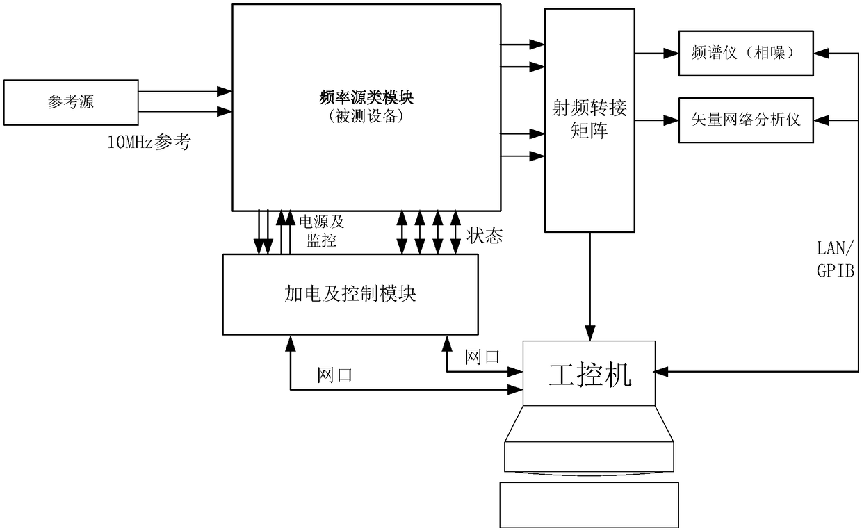
[0030] exist figure 2 In the shown embodiment, when the device under test is a frequency source type radio frequency module, the automatic test device includes a radio frequency transfer matrix for two-way communication with the industrial computer, a power supply and control module and a general measuring instrument, and the device under test The frequency source type RF module provides a reference source of 10MHz reference signal, wherein, the output port of the RF transfer matrix is ​​connected to a general-purpose measuring instrument, and the general-purpose measuring instrument adopts a phase noise spectrum analyzer and a vector network analyzer connected to an industrial computer through LAN / GPIB; plus The power and control module is connected to the industrial computer through the network port, and supplies power to the frequency source RF module through the power supply, control bus and offline control line interface to realize power-on and power-off status control, p...

Embodiment 2

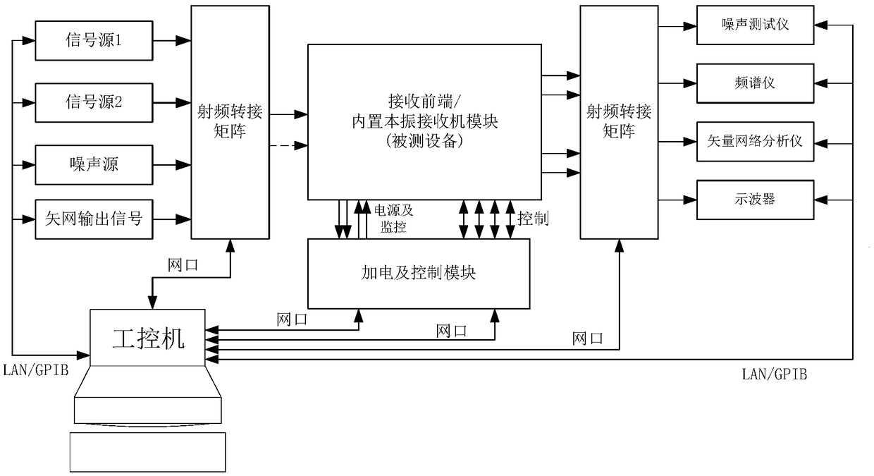
[0032] exist image 3 In another embodiment shown, when the device under test is a receiving front-end / receiver module, the built-in local oscillator receiver, receiving front-end and switch network, etc. do not need an external local oscillator source to cooperate with the radio frequency module test, the automatic test device System composition and figure 1 Similar, only without the need for a multi-channel LO source module. The automatic test device includes: a power-on and control module for two-way communication with the industrial computer through the network port, an input radio frequency transfer matrix module, an output radio frequency transfer matrix module, a radio frequency transfer matrix module, and an industrial computer connected via LAN / GPIB. Signal source 1, signal source 2, noise source, vector network output signal and noise tester, spectrum analyzer, vector network analyzer oscilloscope and other general measuring instruments, in which: the power supply a...

Embodiment 3

[0034] exist Figure 4 In another embodiment shown, when the device under test is a power supply module, the RF transfer matrix in the standard framework of the automatic test device test system is replaced by a power channel switching switch, and the input terminal of the power supply module is connected to power-on and control The module is connected to multi-channel electronic loads, oscilloscopes and other general instruments through the output port of the power channel switch. Under the control of the built-in automatic test software of the industrial computer, the output voltage, output current, power ripple, surge current and Automated testing of indicators such as power efficiency.

[0035] The hardware modules in the automatic test device are, from top to bottom, a 6-in, 6-out 2-group RF transfer matrix, a general power-on control module, and a multi-channel local oscillator module. In the automatic test software debugging mode, on the visual software interface of the ...


PUM


Abstract

The invention discloses a high-coverage automatic radio frequency index test device. By using the device provided by the invention, quick tests with high coverage can be performed on multi-channel radio frequency indexes of various types of equipment under test. The device provided by the invention is implemented via the technical scheme as follows: an input radio frequency interconnection matrixmodule receives multiple signal sources, a noise source and an output signal of a vector network, and provides source signals such as a microwave vector signal source, the noise source and the vectornetwork output signal to the equipment under test; the equipment under test receives a low-phase noise local oscillator signal and a reference clock signal from a multi-channel local oscillator sourcemodule; the equipment under test completes automatic switching of multiple channels via an output radio frequency interconnection matrix module, and transmits a test signal to an universal measurement instrument; an industrial control computer calls control parameters of the universal measurement instrument and the equipment under test to complete automatic test of the multiple indexes, reads a test result of the universal measurement instrument and automatically generates a test report in a standard format; the artificial configuration test and automatic test on the main indexes of the equipment under test are achieved by using a visual manual control interface.

Description

technical field [0001] The invention relates to a fully automatic high-coverage automatic testing device capable of realizing automatic testing of multi-type radio frequency modules and multi-performance indicators, which can be directly applied to automatic high-precision rapid testing of all indicators of various radio frequency modules. Background technique [0002] With the development of testing technology and artificial intelligence, automatic testing technology is gradually getting rid of professional customization and developing towards modularization and generalization. The radio frequency index test in the research and development stage of wireless communication equipment currently mainly adopts a semi-automatic test plan in which testers are on duty throughout the process, and then the test experts manually complete the later data analysis and test problem positioning. The efficiency of the above work cannot fully meet the needs of the current research and develop...

Claims


Application Information

Patent Timeline
Patent Type & Authority Applications(China)
IPC IPC(8): H04W16/18H04W24/08
CPCH04W16/18H04W24/08
Inventor 闫鸿
Owner 10TH RES INST OF CETC
Learn More