High-strength corrosion-resistant heat-insulating horizontal pipe clamp
A corrosion-resistant, horizontal pipe technology, applied in the direction of thermal insulation protection of pipelines, pipeline supports, pipeline protection, etc., can solve the problems of low strength, easy corrosion and high heat loss of thermal insulation pipe clips, and achieve outstanding heat resistance and improved strength. , the effect of low heat loss
- Summary
- Abstract
- Description
- Claims
- Application Information
AI Technical Summary
Problems solved by technology
Method used
Image
Examples
Embodiment 1
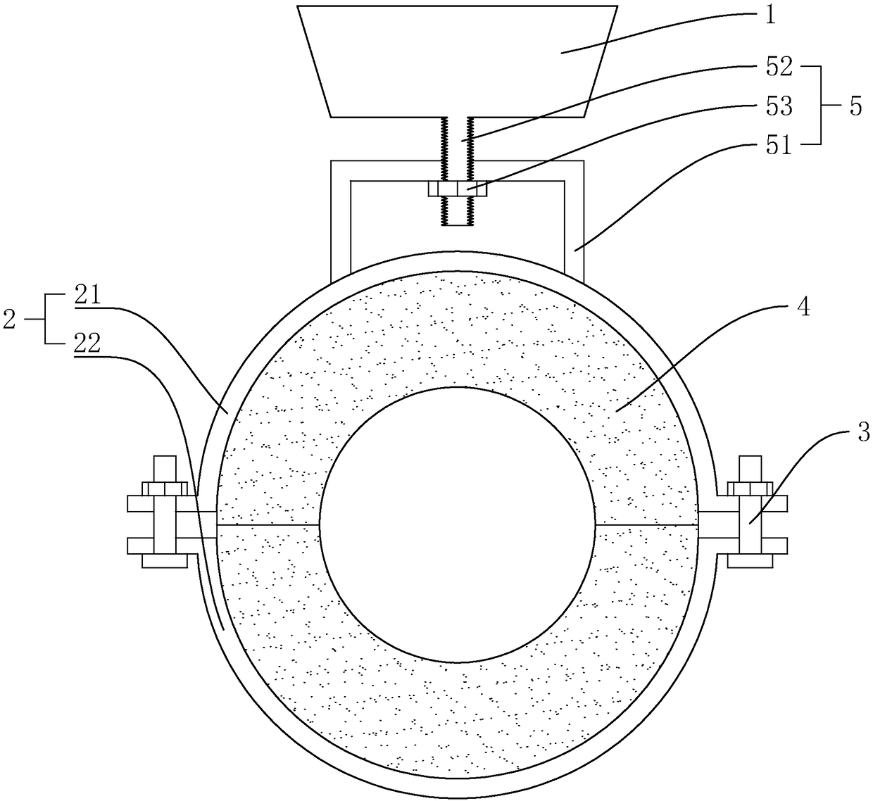
[0025] Example 1: A high-strength corrosion-resistant and heat-insulated horizontal pipe clamp, the structure of which is as follows figure 1 As shown, it includes a pipe clip seat 1, an annular pipe clip 2 composed of an upper pipe clip 21 and a lower pipe clip 22, a fastener 3 and a heat insulation layer 4, and it is characterized in that: the pipe clip seat 1 and the upper pipe An adjustment device 5 for adjusting the height of the annular pipe clamp 2 is provided between the clamps 21. The adjustment device 5 includes a fixed steel plate 51 arranged at the upper end of the upper pipe clamp 21, an adjustment screw arranged at the lower end of the pipe clamp base and pierced through the fixed steel plate 51 52, the adjusting screw 52 is threadedly connected with an adjusting nut 53 that conflicts with the lower side of the fixed steel plate 51.
[0026] The outer side of the annular pipe clamp 2 is provided with a heat-insulating coating, and the heat-insulating coating incl...
Embodiment 2
[0033] Embodiment 2: A high-strength corrosion-resistant and heat-insulating horizontal pipe clamp. The difference from Embodiment 1 is that the selected heat-insulating coating includes the following raw materials in parts by weight: 28 parts of deionized water, 35 parts of elastic acrylic emulsion 2 parts, 2 parts of potassium hexatitanate whiskers, 3 parts of SiO2 airgel, 17 parts of hollow glass microspheres, 5 parts of polytetrafluoroethylene dispersion emulsion, 5 parts of graphite, and 5 parts of additives. The graphite is aphanitic graphite, and the additives include dispersants, defoamers, thickeners and film-forming agents.
Embodiment 3
[0034] Embodiment 3: A high-strength corrosion-resistant and heat-insulating horizontal pipe clamp. The difference from Embodiment 1 is that the selected heat-insulating coating includes the following raw materials in parts by weight: 24 parts of deionized water, 29 parts of elastic acrylic emulsion 5 parts, 5 parts of potassium hexatitanate whiskers, 8 parts of SiO2 airgel, 10 parts of hollow glass microspheres, 9 parts of polytetrafluoroethylene dispersion emulsion, 10 parts of graphite, and 5 parts of additives. The graphite is aphanitic graphite, and the additives include dispersants, defoamers, thickeners and film-forming agents.
PUM
| Property | Measurement | Unit |
|---|---|---|
| Thickness | aaaaa | aaaaa |
Abstract
Description
Claims
Application Information
 - Generate Ideas
- Intellectual Property
- Life Sciences
- Materials
- Tech Scout
- Unparalleled Data Quality
- Higher Quality Content
- 60% Fewer Hallucinations
Browse by: Latest US Patents, China's latest patents, Technical Efficacy Thesaurus, Application Domain, Technology Topic, Popular Technical Reports.
© 2025 PatSnap. All rights reserved.Legal|Privacy policy|Modern Slavery Act Transparency Statement|Sitemap|About US| Contact US: help@patsnap.com


