Trench isolation structure and manufacturing method thereof

A manufacturing method and trench isolation technology, applied in semiconductor/solid-state device manufacturing, semiconductor devices, electrical components, etc., can solve the problems of reduced withstand voltage performance, isolation failure, etc., and achieve the effect of reducing the possibility of leakage

Active Publication Date: 2021-01-05
CSMC TECH FAB2 CO LTD
View PDF10 Cites 0 Cited by
  • Summary
  • Abstract
  • Description
  • Claims
  • Application Information

AI Technical Summary

Problems solved by technology

However, since the performance of high-voltage power devices is quite dependent on isolation technology, especially a large number of hot electrons / holes are formed during device avalanche breakdown, and some of them overcome Si / SiO 2 The potential barrier enters the oxide layer of DTI, and the traps at the oxide layer / polysilicon interface in DTI (the surface density of traps is about E+10 / cm 2 order of magnitude) trapped and drifted by the electric field in polysilicon, causing cross-talk between devices, which can easily lead to isolation failure and reduced withstand voltage performance

Method used


Image

  • Trench isolation structure and manufacturing method thereof
  • Trench isolation structure and manufacturing method thereof
  • Trench isolation structure and manufacturing method thereof

Examples


Embodiment Construction

[0020] In order to facilitate the understanding of the present invention, the present invention will be described more fully below with reference to the associated drawings. A preferred embodiment of the invention is shown in the drawings. However, the present invention can be embodied in many different forms and is not limited to the embodiments described herein. Rather, these embodiments are provided so that the disclosure of the present invention will be thorough and complete.

[0021] Unless otherwise defined, all technical and scientific terms used herein have the same meaning as commonly understood by one of ordinary skill in the technical field of the invention. The terms used herein in the description of the present invention are for the purpose of describing specific embodiments only, and are not intended to limit the present invention. As used herein, the term "and / or" includes any and all combinations of one or more of the associated listed items.
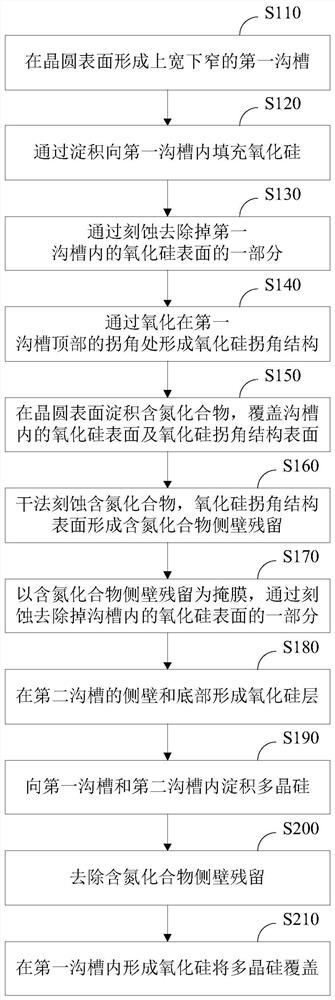
[0022] The se...


PUM

PropertyMeasurementUnit
depthaaaaaaaaaa
depthaaaaaaaaaa
thicknessaaaaaaaaaa

Abstract

The invention relates to a trench isolation structure and a manufacturing method thereof. The method comprises: forming a shallow trench with a wide top and a narrow bottom on the surface of a wafer; filling the shallow trench with silicon oxide by depositing; removing a part of the oxide by etching Silicon; form a silicon oxide corner structure at the corner of the top of the shallow trench by thermal oxidation; deposit silicon nitride on the wafer surface to cover the silicon oxide surface and the silicon oxide corner structure surface in the shallow trench; dry etch silicon nitride , removing the silicon nitride on the surface of the silicon oxide in the shallow groove, and forming a silicon nitride residue extending into the groove on the surface of the silicon oxide corner structure; using the silicon nitride residue as a mask, continue to etch downward to form a deep groove; Forming a silicon oxide layer on the sidewall and bottom of the deep trench; depositing polysilicon into the shallow and deep trenches; removing silicon nitride; forming silicon oxide in the shallow trench to cover the polysilicon. The shallow groove of the present invention has a relatively large size, and the formed trench isolation structure can reduce the possibility of electric leakage caused by high-voltage wiring above the trench isolation structure.

Description

technical field [0001] The invention relates to the field of semiconductor manufacturing, in particular to a method for manufacturing a trench isolation structure, and also to a trench isolation structure. Background technique [0002] In the fields of intelligent power management, display, motor drive and automotive electronics, the requirements for high efficiency and energy saving are increasing day by day. The field of high-voltage power has also derived different types such as LDMOS (lateral double-diffused metal oxide semiconductor field effect transistor), LIGBT (lateral insulated gate bipolar transistor), power-DMOS (power-double diffused metal oxide semiconductor field effect transistor), etc. The voltage level and device structure of different structures have a withstand voltage ranging from tens of volts to hundreds of volts. Therefore, various terminal structures such as field plates and field rings and RESURF (reduced surface electric field) technology have been...

Claims


Application Information

Patent Timeline
Patent Type & Authority Patents(China)
IPC IPC(8): H01L21/762
CPCH01L21/76224H01L21/76232H01L21/76235H01L21/76237H01L21/02164H01L21/02236H01L21/02255H01L21/02274H01L21/26513H01L21/31053H01L21/31116H01L21/32H01L21/761H01L29/0646H01L29/0649
Inventor 祁树坤
Owner CSMC TECH FAB2 CO LTD
Why Eureka
Try Eureka