
Hand carving knife

A kind of engraving knife and manual technology, applied in the direction of artist's hand tools, decorative arts, etc., can solve the problems of difficult cutting edge 51 cutting process, difficult control of operation accuracy, etc., to achieve convenient cutting work, reduce precision control requirements, high surface quality quality effect

Active Publication Date: 2019-01-11
苏州中航盛世刀辊制造有限公司
View PDF10 Cites 0 Cited by
  • Summary
  • Abstract
  • Description
  • Claims
  • Application Information

AI Technical Summary

Problems solved by technology

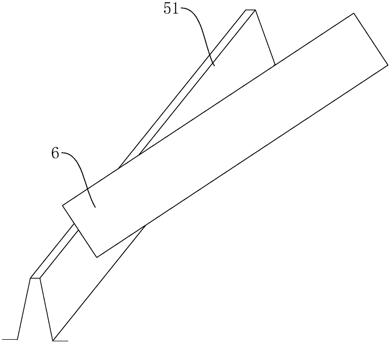
As attached to the manual figure 2 As shown, the cutter head 6 of the existing manual carving knife is at a right angle, and when it is stretched into the side wall of the cutting edge 51 and the side wall is directly polished and opened, it is considered that when a normal worker holds a manual carving knife, the arm lifts up. angle, the upper half of the cutting edge 6 toward the end of the cutting edge 51 to be processed sometimes first contacts the side wall of the cutting edge 51, which will inevitably cause the side wall of the cutting edge 51 to be polished by the cutting edge 6 to form a step with a larger slope However, according to the requirements of the cutting edge 51, it is necessary to repeatedly grind and repair the step surface, and the operation accuracy is difficult to control, which makes the whole cutting edge 51's fronting process more difficult.

Method used


Image

  • Hand carving knife
  • Hand carving knife
  • Hand carving knife

Examples


Embodiment

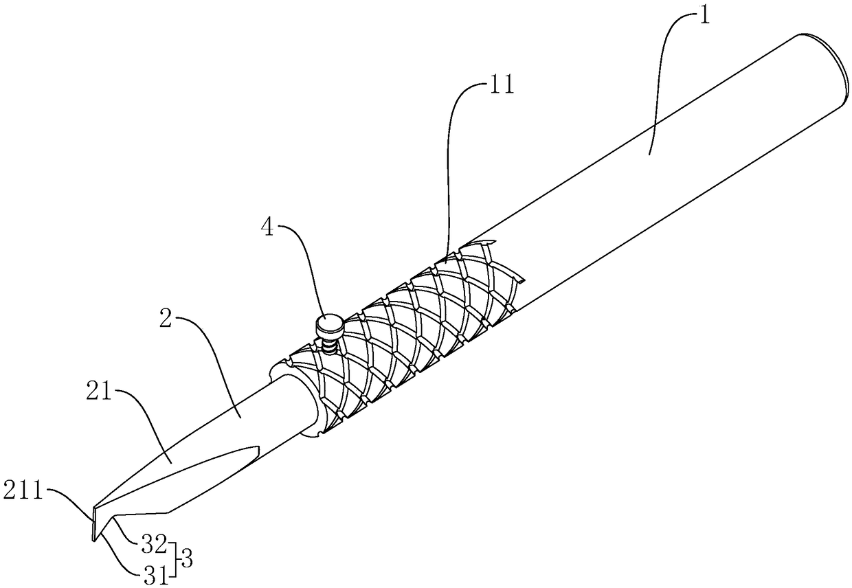
[0035] Such as image 3 Shown, be a kind of manual engraving knife disclosed by the present invention, comprise handle of a knife 1 and cutter 2, one end of cutter 2 is inserted in the cutter 2, and the other end is provided with and is used for die-cutting roller 5 (referring to figure 1 ) on the cutting edge 51 (see figure 2 ) to carry out the blade section 21 of opening, the length of the blade section 21 is 12mm-15mm. The tool 2 and the tool handle 1 are coaxially arranged, and the side wall of the tool handle 1 is threadedly connected with a locking bolt 4, and one end of the locking bolt 4 screwed into the tool handle 1 abuts against the side wall of the tool 2; 1. A knurling section 11 for increasing friction is also provided on the side wall near the end of the tool 2, so as to increase the stability of the worker when holding the tool handle 1 while working.

[0036] Such as image 3 As shown, the end face of the blade section 21 away from the handle 1 is defined ...


PUM

PropertyMeasurementUnit
Widthaaaaaaaaaa

Abstract

The invention discloses a hand carving knife, and belongs to the field of machining tools for die-cutting knife rollers. The hand carving knife comprises a knife handle and a knife body mounted on theknife handle. A blade section used for sharpening an upper cutting edge of a die-cutting knife roller is arranged at the end, away from the knife handle, of the knife body. The end face, away from the knife handle, of the blade section of is a blade face. An included angle between the blade face and the plane perpendicular to the length direction of the blade section is 4-8 degrees. The inclination direction of the blade face is the same as that of the side face of the upper cutting edge of the die-casting knife roller. The hand carving knife has the effect that the operation accuracy duringsharpening polishing of the cutting edge can be easily controlled, and thus, sharpening is convenient.

Description

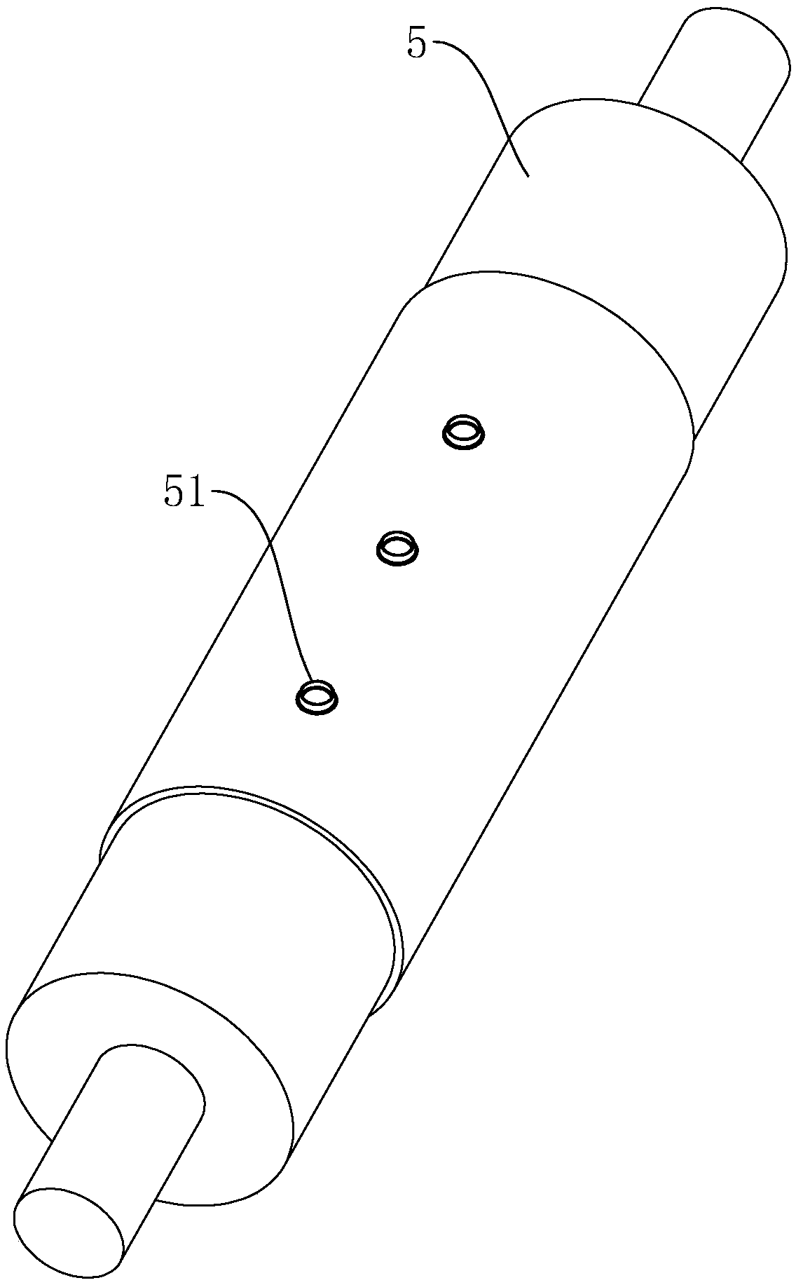
technical field [0001] The invention relates to the field of die cutter roller processing tools, in particular to a manual engraving knife. Background technique [0002] The die-cutting knife roll is a high-efficiency die-cutting tool that processes and shapes the cutting edge on a circular shaft and replaces flat-pressing and punching. It is mainly used in printing, mobile phone accessories manufacturing, paper packaging, non-woven fabrics and other industries. [0003] Different product processing, the designed edge shape is not the same. In the prior art, if the specification attached figure 1 with 2 As shown, the cutting edge 51 on the die cutter roller 5 is usually milled out by a milling machine, and then the cutting edge 51 is sharpened (even if the edge width of the cutting edge 51 is infinitely close to 0) before the product can be processed. Make a cut. However, affected by the processing accuracy of traditional milling machines, the edge width of cutting edge ...

Claims


Application Information

Patent Timeline
IPC IPC(8): B44B11/00B44B11/02
CPCB44B11/00B44B11/02
Inventor 周立国
Owner 苏州中航盛世刀辊制造有限公司
Learn More