
Film tearing device and film tearing method thereof

A film device and roll film technology, applied in chemical instruments and methods, layered products, lamination auxiliary operations, etc., can solve the difficult and efficient peeling and removal of tearing film means, weak bonding performance, time-consuming and labor-intensive and other problems to achieve the effect of saving manpower, good integrity and convenient operation

Inactive Publication Date: 2019-01-11
ZHEJIANG JINKO SOLAR CO LTD +1
View PDF3 Cites 9 Cited by
  • Summary
  • Abstract
  • Description
  • Claims
  • Application Information

AI Technical Summary

Problems solved by technology

For the protective film for temporary protection, due to its weak adhesive performance, the existing tape can be used to lift the edge, and then the protective film can be separated by reel or air knife blowing; but this method is only suitable for the adhesion with the workpiece. Smaller protective film is peeled off. For the case where the protective film and the workpiece are bonded as a whole by organic packaging materials, due to the excellent packaging performance, the protective film is bonded very firmly. It is difficult to use manual heating to peel off the film. High-efficiency stripping removal may cause damage to the workpiece during the process. If the smooth progress of the entire process is not used, the operation is difficult, time-consuming, labor-intensive, inefficient, and there is a risk of being burned, which is not conducive to the process.

Method used


Image

  • Film tearing device and film tearing method thereof
  • Film tearing device and film tearing method thereof
  • Film tearing device and film tearing method thereof

Examples


Embodiment Construction

[0037] The following will clearly and completely describe the technical solutions in the embodiments of the present invention with reference to the accompanying drawings in the embodiments of the present invention. Obviously, the described embodiments are only some, not all, embodiments of the present invention. Based on the embodiments of the present invention, all other embodiments obtained by persons of ordinary skill in the art without making creative efforts belong to the protection scope of the present invention.

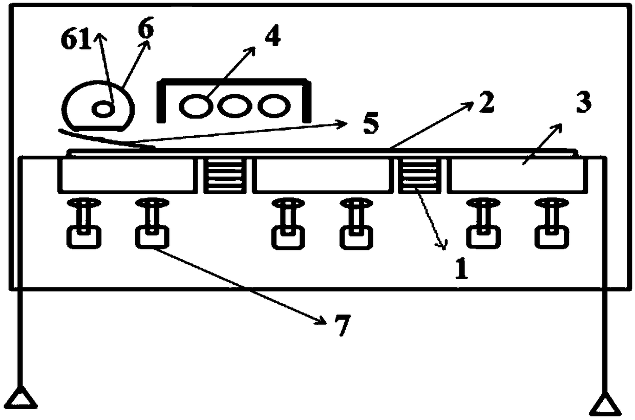
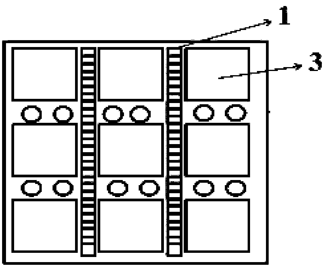
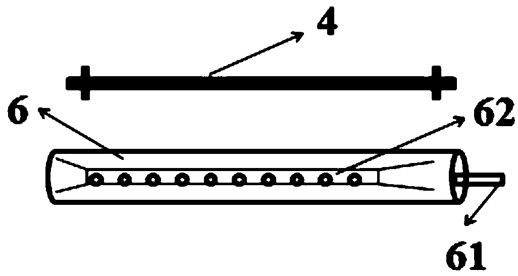
[0038] The invention provides a film tearing device, such as Figure 1 to Figure 3 shown, including:

[0039] The liftable conveying device 1 is used to convey the workpiece 2 to be torn off;

[0040] The heating platform 3 is located between two adjacent liftable conveying devices 1, and is used to place and heat the workpiece 2;

[0041] The top auxiliary heating part 4 is located above the heating platform 3 and is used to directly heat the protective fil...


PUM


Abstract

The invention discloses a film tearing device and a film tearing method thereof. The device comprises: lifting conveyers, which is used for conveying a workpiece of a film to be torn; a heating platform, which is located between two adjacent lifting conveyers and used for placing and heating the workpiece; a top auxiliary heating component, which is located above the heating platform and used fordirectly heating the protective film on the workpiece; and a film roller, which is located at one end of the heating platform, includes a vacuum pipe (equipped with multiple vacuum suction pipes and extending through the interior of the heating platform), and is used for adsorbing the protective film through the vacuum suction pipes, winding the adsorbed protective film by rolling and integrally peeling off the protective film. By simultaneous heating of the workpiece and vacuum adsorption for film tearing up and down, the above film tearing device can help reduce the bonding performance between the protective film and the workpiece, is beneficial to automatic or semi-automatic peeling of various protective films on the surface of the workpiece, is convenient and fast to operate, has highheating efficiency, achieves the purpose of efficient film tearing, and saves lots of manpower and material costs.

Description

technical field [0001] The invention relates to the field of film tearing technology, in particular to a film tearing device and a film tearing method thereof. Background technique [0002] In the production process of surface mount technology, key equipment such as chip mounters are often used to apply films to the workpieces produced for dust prevention and protection, and the pasted protective films often need to be peeled off or replaced later. For the protective film for temporary protection, due to its weak adhesive performance, the edge can be raised by the existing tape sticking method, and then the protective film can be separated by reel or air knife blowing; but this method is only suitable for the adhesion with the workpiece. Smaller protective film is peeled off. For the case where the protective film and the workpiece are bonded as a whole by organic packaging materials, due to the excellent packaging performance, the protective film is bonded very firmly, and ...

Claims


Application Information

Patent Timeline
IPC IPC(8): B32B38/10
CPCB32B38/10
Inventor 孙长振王娟郭志球尹家祥汪红
Owner ZHEJIANG JINKO SOLAR CO LTD
Learn More