
Cooling circulating main shaft box of numerical control machining center

A cooling cycle and headstock technology, applied in metal processing equipment, metal processing machinery parts, manufacturing tools, etc., can solve problems such as shortening the service life of machine tools, affecting the machining accuracy of machine tools, locking the machine tool spindle, etc., to improve the cooling effect, Good cooling effect and the effect of improving the precision of machining

Inactive Publication Date: 2019-01-08
黄石市友嘉智能科技有限公司
View PDF1 Cites 2 Cited by
  • Summary
  • Abstract
  • Description
  • Claims
  • Application Information

AI Technical Summary

Problems solved by technology

[0002] CNC machine tools will generate heat with the rotation of the spindle during processing, especially for high-speed machine tools, whose spindle speed is high and generate more heat. If it is not cooled in real time, it will seriously affect the machining accuracy of the machine tool and shorten the service life of the machine tool , and even cause the machine tool spindle to "lock" due to thermal expansion
The existing machine tool cooling method mainly adopts a separately configured oil cooler, which takes away the heat of the lubricating oil in the main shaft oil tank through the oil cooler, and keeps the oil temperature of the lubricating oil in the main shaft oil tank suitable. The cooling effect is good, but the price is expensive. , high input costs, difficult for customers to accept
In view of its defects, Chinese patent application number "201520409846.0" proposes a "spindle casting with cooling structure", which discloses a main shaft casting body with circulation grooves on both sides, and adopts the method of cooling liquid flowing through the circulation groove To achieve the purpose of cooling the spindle, it simplifies the cooling structure of the original machine tool spindle and reduces the input cost, but its cooling effect is poor and the efficiency is low

Method used


Image

  • Cooling circulating main shaft box of numerical control machining center
  • Cooling circulating main shaft box of numerical control machining center
  • Cooling circulating main shaft box of numerical control machining center

Examples


Embodiment Construction

[0015] The following will clearly and completely describe the technical solutions in the embodiments of the present invention with reference to the accompanying drawings in the embodiments of the present invention. Obviously, the described embodiments are only some, not all, embodiments of the present invention. Based on the embodiments of the present invention, all other embodiments obtained by persons of ordinary skill in the art without making creative efforts belong to the protection scope of the present invention.

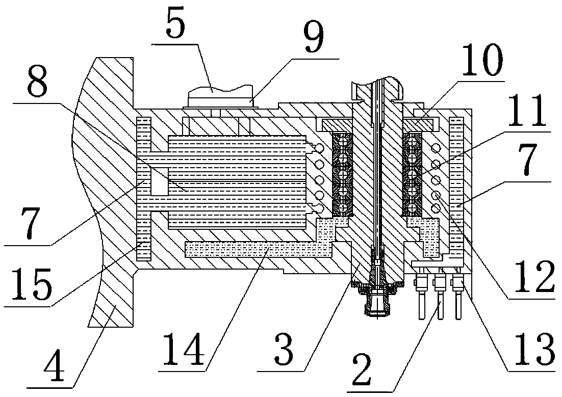
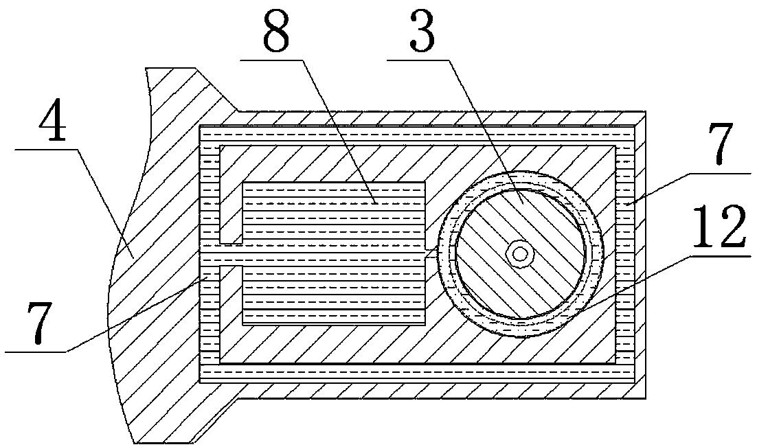
[0016] refer to figure 1 and figure 2 , a cooling cycle headstock of a CNC machining center, comprising a headstock body 4, a main shaft 3, a bearing 11 and a bearing cover 10, the bearing 11 is arranged inside the headstock body 4, and the main shaft 3 is set on the Inside the bearing 11, the bearing cover 10 is set outside the main shaft 3, and the lower end of the bearing cover 10 is against the upper end of the bearing 11. A circulating water channel 7 i...


PUM


Abstract

The invention discloses a cooling circulating main shaft box of a numerical control machining center. The cooling circulating main shaft box of the numerical control machining center comprises a mainshaft box body, a main shaft, a bearing and a bearing cover; a circulating water way is formed around the main shaft box body; a water storage tank is arranged on one side in the main shaft box body;the circulating water way penetrates through the water storage tank; a spiral cooling water pipe is wound at the external of the bearing; the cooling water pipe communicates with the water storage tank; the circulating water way, the water storage tank and the cooling water pipe form a cooling channel; an electromagnetic switch is arranged at the lower part of one end of the main shaft box body, and communicates with the circulating water way; the lower end of the electromagnetic switch communicates a cooling nozzle; and the circulating water way, the electromagnetic switch and the cooling nozzle form another cooling channel. The cooling effect and the machining precision of a machine tool main shaft are improved; the service life of the main shaft and a cutter is prolonged; and the production and investment cost is reduced.

Description

【Technical field】 [0001] The invention relates to the technical field of mechanical processing equipment, in particular to a cooling cycle spindle box of a numerical control machining center. 【Background technique】 [0002] CNC machine tools will generate heat with the rotation of the spindle during processing, especially for high-speed machine tools, whose spindle speed is high and generate more heat. If it is not cooled in real time, it will seriously affect the machining accuracy of the machine tool and shorten the service life of the machine tool , and even cause the machine tool spindle to "lock" due to thermal expansion. The existing machine tool cooling method mainly adopts a separately configured oil cooler, which takes away the heat of the lubricating oil in the main shaft oil tank through the oil cooler, and keeps the oil temperature of the lubricating oil in the main shaft oil tank suitable. The cooling effect is good, but the price is expensive. , High input cos...

Claims


Application Information

Patent Timeline
Patent Type & Authority Applications(China)
IPC IPC(8): B23Q11/12B23Q11/10B23B19/00
CPCB23Q11/127B23Q1/70B23Q11/10
Inventor 方辉
Owner 黄石市友嘉智能科技有限公司
Learn More