Cooling device for automobile part machining

A technology for cooling devices and spare parts, which is applied in cooling fluid circulation devices, household refrigeration devices, lighting and heating equipment, etc. It can solve the problems of cumbersome work and manual control of the opening and closing of cooling nozzles, so as to improve the effect of finished products and reduce work content, effect of improving compactness

Pending Publication Date: 2022-04-08
重庆乐迪龙鑫科技股份有限公司
View PDF2 Cites 0 Cited by
  • Summary
  • Abstract
  • Description
  • Claims
  • Application Information

AI Technical Summary

Problems solved by technology

[0003] The purpose of the present invention is to solve the problem that in the traditional cooling process of auto parts, technicians need to manually control the opening and closing of the cooling nozzle, and the work is cumbersome.

Method used


Image

  • Cooling device for automobile part machining
  • Cooling device for automobile part machining
  • Cooling device for automobile part machining

Examples


Embodiment Construction

[0025] In order to further explain the technical means and effects of the present invention to achieve the intended purpose of the invention, the specific implementation, structure, features and effects of the present invention will be described in detail below in conjunction with the accompanying drawings and preferred embodiments.

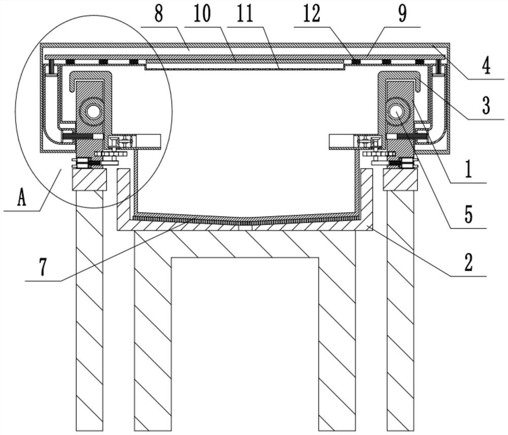
[0026] The reference signs in the drawings of the description include: guide rail 1, slag discharge tank 2, sliding seat 3, sprinkler table 4, lead screw 5, timing belt 6, connecting rod 7, sprinkler chamber 8, sealing plate 9, sealing plug 10, Outlet plate 11, second return spring 12, transmission shaft 13, rack 14, gear 15, cam 16, first piston rod 17, piston chamber 18, connecting block 19, second piston rod 20, L-shaped air bag 21, the first Three piston rods 22, fan 23.

[0027] Auto parts processing cooling device, for example figure 1 and figure 2 As shown: it includes a symmetrically arranged guide rail 1, a bearing mechanism that is s...


PUM


Abstract

The invention relates to the technical field of automobile part machining, and particularly discloses an automobile part machining cooling device which comprises symmetrically-arranged guide rails, a bearing mechanism slidably connected with the guide rails and a driving mechanism driving the bearing mechanism to slide, the bearing mechanism comprises a sliding seat, a mounting groove and a gear, the mounting groove and the gear are arranged on the sliding seat, and racks are arranged on the side walls of the guide rails. A piston cavity is formed in the guide rail and communicates with a water inlet pipe and a water outlet pipe, a first piston rod is slidably connected into the piston cavity in a sealed mode, a first reset spring is arranged between the first piston rod and the piston cavity, and the free end of the first piston rod extends out of the piston cavity and the side wall of the guide rail. A water spraying table is arranged above the guide rail, a water spraying cavity communicated with the free end of the water outlet pipe is formed in the water spraying table, a plurality of water spraying holes communicated with the water spraying cavity are formed in the lower surface of the water spraying cavity, and the problems that in the traditional automobile part cooling process, technicians need to manually control opening and closing of cooling spray heads, and work is tedious are solved.

Description

technical field [0001] The application relates to the technical field of auto parts processing, and specifically discloses a cooling device for auto parts processing. Background technique [0002] After polishing the auto parts, it is necessary to cool down the auto parts before entering the next process. As the number of auto parts increases, the cooling effect of the coolant in the cooling pool will decrease, and the replacement of the coolant in the cooling pool is also more troublesome. The replacement process is complicated, and the cooling pool needs to be drained, cleaned and refilled. The process is cumbersome. It takes a long time, and another way is to use cooling nozzles to cool down. This method requires technicians to put the polished auto parts on a fixed shelf, and then turn on the cooling nozzles to cool down. This method requires technicians to manually adjust the zero temperature. Fixing the accessories, and manually controlling the opening and closing of ...

Claims


Application Information

Patent Timeline
Patent Type & Authority Applications(China)
IPC IPC(8): F25D31/00F25D25/04F25D17/02F25D17/06B08B1/00
Inventor 李欢
Owner 重庆乐迪龙鑫科技股份有限公司
Why Eureka
Try Eureka