
Manufacturing and forming process for oil pump rotor

A molding process and oil pump technology, applied in the direction of manufacturing tools, metal processing equipment, sawing machine accessories, etc., can solve the problems of reducing the production efficiency of the outer rotor of the oil pump, reducing the cutting quality, and polluting the working environment, so as to prevent pollution of the working environment , improve cutting quality and improve efficiency

Inactive Publication Date: 2021-10-19
李宜宜
View PDF14 Cites 0 Cited by
  • Summary
  • Abstract
  • Description
  • Claims
  • Application Information

AI Technical Summary

Problems solved by technology

[0006] The present invention can solve the following problems that may be encountered in the cutting process of the existing oil pump outer rotor embryo body: a. The cylindrical outer rotor embryo body is clamped and fixed by manual use of clamps, thereby cutting it, After each cutting, the fixture needs to be disassembled again before cutting again, which is time-consuming and laborious, resulting in low cutting efficiency, thereby reducing the production efficiency of the outer rotor of the oil pump; b. when cutting, the existing cutting equipment Usually, the way of spraying coolant to the cutting tool is used for cooling, resulting in a large amount of coolant and cutting chips attached to the surface of the cut blank, which reduces the quality of cutting. At the same time, the outflow of coolant will pollute the working environment. Follow-up cleaning caused inconvenience

Method used


Image

  • Manufacturing and forming process for oil pump rotor
  • Manufacturing and forming process for oil pump rotor
  • Manufacturing and forming process for oil pump rotor

Examples


Embodiment Construction

[0038] Embodiments of the present invention will be described below with reference to the drawings. In the process, in order to ensure the clarity and convenience of illustration, we may exaggerate the width of the lines or the size of the constituent elements in the diagram.

[0039] In addition, the following terms are defined based on the functions in the present invention, and may be different according to the user's or operator's intention or practice. Therefore, these terms are defined based on the entire content of this specification.

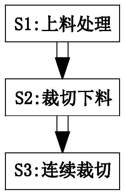
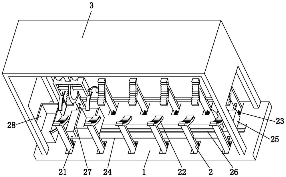
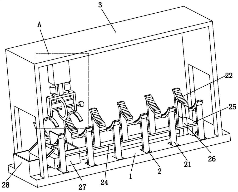
[0040] Such as Figure 1 to Figure 9 As shown, an oil pump rotor manufacturing and molding process uses a kind of oil pump rotor manufacturing and molding equipment. The oil pump rotor manufacturing and molding equipment includes a bottom plate 1, a support device 2 and a cutting device 3. The specific method of processing the rotor embryo body is as follows:

[0041] S1. Feeding process: manually place the outer rotor body of the oil...


PUM


Abstract

The invention relates to a manufacturing and forming process for an oil pump rotor, which comprises a bottom plate, a supporting device and a cutting device. The manufacturing and forming process can solve the problems that in the cutting process of an existing oil pump outer rotor blank, a, the cylindrical outer rotor blank is manually clamped and fixed through a clamp so that the outer rotor blank can be cut, the clamp needs to be disassembled again after cutting every time, then cutting can be conducted again, time and labor are wasted, the cutting efficiency is low, and the production efficiency of the oil pump outer rotor is reduced; and b, during cutting, conventional cutting equipment generally adopts a mode of spraying cooling liquid to a cutting tool for cooling, so that a large amount of cooling liquid and cutting chips are attached to the surface of cut small-section blanks, the cutting quality is reduced, and meanwhile, the working environment is polluted due to outflow of the cooling liquid, and inconvenience is caused to subsequent cleaning.

Description

technical field [0001] The invention relates to the field of manufacturing and molding of oil pump rotors, in particular to a manufacturing and molding process of oil pump rotors. Background technique [0002] The rotor oil pump consists of a housing, an inner rotor, an outer rotor and a pump cover. The inner rotor is fixed on the rotor shaft with keys or pins, and is directly or indirectly driven by the crankshaft gear. When the inner rotor and the outer rotor are installed, there will be a certain eccentricity between the two centers, and the rotation of the inner rotor will drive the outer rotor along the Rotate in the same direction to realize the oil supply process. [0003] During the manufacturing process of the outer rotor, it is usually necessary to first cut the cylindrical outer rotor body into small sections at a fixed length, and further process the cut sections to obtain a formed outer rotor. [0004] At present, the existing oil pump outer rotor embryo body ...

Claims


Application Information

Patent Timeline
Patent Type & Authority Applications(China)
IPC IPC(8): B23D47/04B23D47/12B23D59/02B23D59/00
CPCB23D47/04B23D47/042B23D47/12B23D59/02B23D59/006
Inventor 李宜宜
Owner 李宜宜
Learn More