
A kind of air cooling device for heat treatment workpiece

A technology of air-cooling device and blowing device, which is applied in the field of cooling workpieces after heating in heat treatment furnaces. It can solve problems such as shaking, long time spent, and damage to workpieces, and achieve uniform cooling, easy left and right movement, and guaranteed effects.

Active Publication Date: 2015-10-28
JOUDER PRECISION INDAL KUSN
View PDF3 Cites 0 Cited by
  • Summary
  • Abstract
  • Description
  • Claims
  • Application Information

AI Technical Summary

Problems solved by technology

[0002] The heat treatment furnace is an industrial furnace for performing various metal heat treatments on metal workpieces. After the heat treatment of various workpieces, it needs to be cooled before the next operation process. At present, the cooling of heat treated workpieces generally adopts the method of horizontal air cooling. That is to say, the fan and the heat treatment workpiece are at the same level, and the fan is used to cool the heat treatment workpiece with the horizontal wind blown out, but this cooling method has the following problems: ① The lateral air blowing makes the side of the heat treatment workpiece facing the fan cool faster, while The side facing away from the fan cools slowly. Due to uneven cooling, the internal structure hardness of the heat-treated workpiece is inconsistent during the cooling process, which affects the quality of the heat-treated workpiece; ②It takes a long time for the fan to blow horizontally for cooling; When it is small, the horizontal blowing will cause the heat treatment workpiece to shake during the cooling process, which will easily cause the heat treatment workpiece to tilt to one side and fall down, causing damage to the workpiece

Method used


Image

  • A kind of air cooling device for heat treatment workpiece
  • A kind of air cooling device for heat treatment workpiece

Examples


Embodiment Construction

[0017] The present invention will be further described below in conjunction with the drawings.

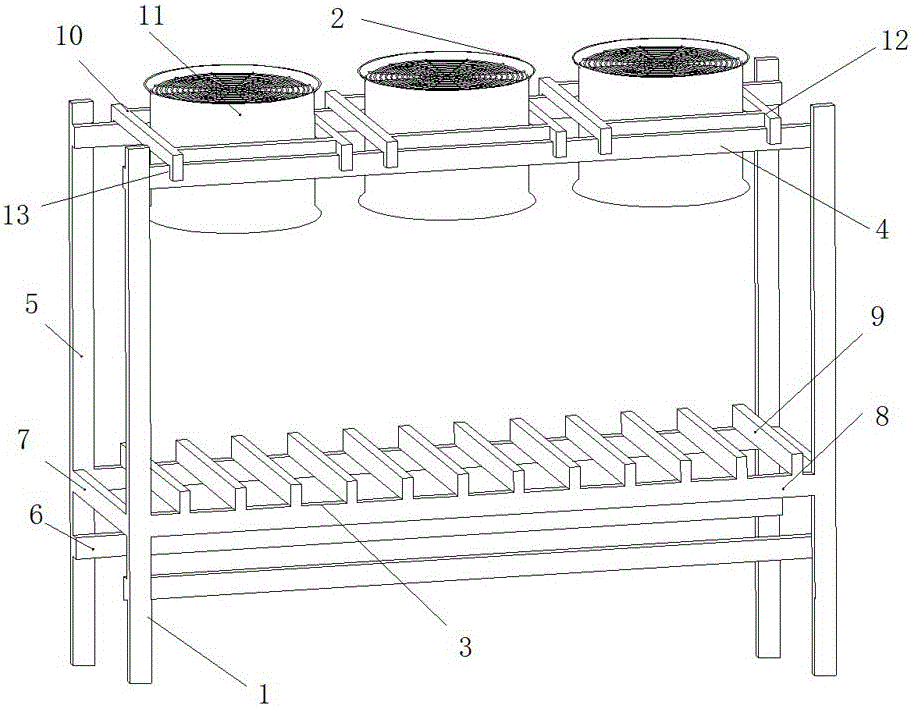
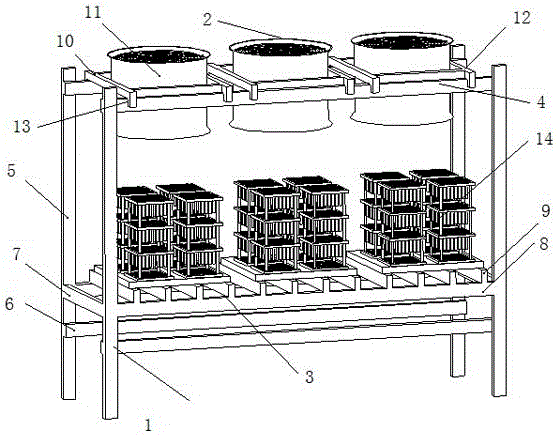
[0018] Such as figure 1 with figure 2 As shown, an air-cooling device for heat-treating workpieces includes a supporting device 1 and a blowing device 2 arranged on the supporting device 1. The supporting device 1 is used to support the fixed blowing device 2 to ensure the stability of the air-cooling process. The lower end is provided with a placing part 3 for placing the workpiece 14, and a blowing device 2 for cooling the workpiece 14 is provided above the placing portion 3. The blowing device 2 vertically faces the placing portion 3 to facilitate vertical blowing to cool the workpiece 14. Blowing air will not cause the workpiece 14 to sway and cause the risk of falling and damage. The cooling air uses air to take away the temperature of the workpiece 14 from top to bottom to achieve the cooling effect, and the cooling wind passes through the circumference of the workpiece 14 to e...


PUM


Abstract

The invention discloses an air cooling device for heat treatment of a workpiece, which comprises a support device and a plurality of air blowing devices arranged on the support device, wherein the lower end of the support device is provided with a bearing part for bearing a workpiece; the air blowing devices for cooling the workpiece are arranged above the bearing part; the upper end of the support device is provided with a first cross beam; and the air blowing devices are arranged on the first cross beam in a movable manner. The air cooling device for heat treatment of a workpiece is simple in structure, convenient to manufacture and uniform in workpiece cooling, and enhances the cooling quality, thereby enhancing the quality of the workpiece, and reducing the deformation and rejection of the workpiece. Thus, the air cooling device has favorable popularization value.

Description

Technical field [0001] The invention relates to the cooling of a workpiece after heating in a heat treatment furnace, in particular to an air cooling device for heat treatment of the workpiece. Background technique [0002] The heat treatment furnace is an industrial furnace that performs various metal heat treatments on metal workpieces. After heat treatment of various workpieces, they need to be cooled before the next operation process can be carried out. At present, the cooling of heat treatment workpieces generally adopts transverse air cooling. That is, the fan and the heat-treated workpiece are in the same horizontal plane, and the fan is used to cool the transverse wind blown out of the heat-treated workpiece. However, this cooling method has the following problems: ①The lateral blowing makes the side of the heat-treated workpiece facing the fan cool faster, and The side facing away from the fan cools more slowly. Due to the uneven cooling, the internal structure hardness ...

Claims


Application Information

Patent Timeline
Patent Type & Authority Patents(China)
IPC IPC(8): C21D1/00C21D1/84
Inventor 王仲伟楊天文曹峰
Owner JOUDER PRECISION INDAL KUSN
Learn More