
A metal cylinder electrofusion additive manufacturing system

An additive manufacturing and metal cylinder technology, which is applied in the field of metal cylinder electrofusion additive manufacturing system, can solve the problems of complex manufacturing process, low material utilization rate, long production cycle, etc. Good performance and chemical properties, ensuring the effect of uniformity

Active Publication Date: 2019-07-26
NANFANG ADDITIVE MFG TECH
View PDF6 Cites 0 Cited by
  • Summary
  • Abstract
  • Description
  • Claims
  • Application Information

AI Technical Summary

Problems solved by technology

At present, the metal cylinder is mainly manufactured by forging and pressing forming methods of heavy forging industrial equipment such as hundreds of tons of large-scale steel ingot smelting, casting and 10,000-ton hydraulic press, supplemented by final machining. This method can basically meet the technical quality requirements, but this manufacturing Numerous processes, long production cycle, and low material utilization rate will inevitably lead to high component costs. On the other hand, the manufacturing process is complicated, and chemical and mechanical properties are difficult to control, which also results in poor quality stability, high scrap rate, and high prices. and other issues seriously affect the progress of project construction and restrict the development of my country's heavy equipment manufacturing industry

Method used


Image

  • A metal cylinder electrofusion additive manufacturing system
  • A metal cylinder electrofusion additive manufacturing system
  • A metal cylinder electrofusion additive manufacturing system

Examples


Embodiment example

[0038] [Implementation case] Production of rotating cylinder

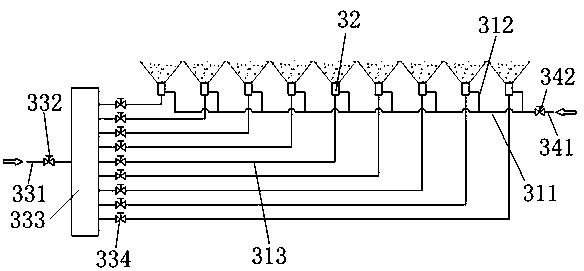
[0039] This case describes the process of making a metal cylinder by electrofusion forming. The material is ordinary low carbon steel. For the equipment used, see the attached figure 1 .

[0040] Attached figure 1 This is a schematic explanatory diagram of this embodiment, in which the cooling device only draws 9 nozzles 32 in this schematic diagram, and the number that meets the requirements can be selected according to specific needs during implementation, and the power supply, automatic wire feeding and other devices are omitted in the figure.

[0041] Specifically, ordinary low-carbon steel is selected as the raw material wire, the diameter of the raw wire is 4mm, the electrofusion head assembly 2 includes 9 electrofusion heads, the electrofusion power source is a DC power source, and the electrofusion head is connected to the negative electrode of the power source. Connect the positive pole of the power supply (when ...


PUM

PropertyMeasurementUnit
diameteraaaaaaaaaa
diameteraaaaaaaaaa

Abstract

The invention discloses a metal cylinder electric smelting additive manufacturing system. The metal cylinder electric smelting additive manufacturing system comprises a cylindrical base body, an electric smelting head component, a cooling device and a horizontal moving drive device; the cooling device comprises an integration part arranged in the base body, a plurality of nozzles sequentially arranged in the length direction of the integration part, a water inlet part arranged at one end of the integration part and an air inlet part arranged at the other end of the integration part; the integration part is internally provided with a ventilation main pipe, ventilation branch pipes communicated with the ventilation main pipe with the nozzles, and a plurality of independent water passing ways in one-to-one correspondence connection with the nozzles, and the water inlet part comprises a water inlet main pipe, a stop valve used for controlling the water inlet main pipe to be on and off, a distributor used for distributing water of the water inlet main pipe to the independent water passing ways, and water amount adjusting valves arranged on the independent water passing ways. The air inlet part comprises an air inlet pipe communicated with the ventilation main pipe and an air amount adjusting valve arranged on the air inlet pipe. The metal cylinder electric smelting additive manufacturing system can achieve rapid precise cooling.

Description

Technical field [0001] The invention relates to the field of additive manufacturing equipment, in particular to a metal cylinder electrofusion additive manufacturing system. Background technique [0002] At present, modern heavy industrial equipment such as nuclear power, thermal power, petrochemical, metallurgy, and shipbuilding is developing rapidly in the direction of large-scale, complex, high-performance parameters and high reliability and long-life service under extreme conditions. Low-alloy high-strength steel is required , Heat-resistant alloys and other key metal cylinder components are getting larger and larger, and the quality requirements are getting higher and higher. Nowadays, heavy forging industrial equipment such as hundreds of tons of large steel ingot smelting, casting and 10,000 tons hydraulic press are mainly used to manufacture metal cylinders, supplemented by final machining. This method can basically meet the technical quality requirements, but this manufa...

Claims


Application Information

Patent Timeline
Patent Type & Authority Patents(China)
IPC IPC(8): B22F3/115
CPCB22F3/115
Inventor 卢迪严连菊朱晓强朱晓龙杨晓宜
Owner NANFANG ADDITIVE MFG TECH
Learn More