
A multi-objective optimization automatic mapping scheduling method for row-column parallel coarse-grained reconfigurable arrays

A multi-objective optimization and automatic mapping technology, applied in multi-programming devices, program startup/switching, program control design, etc., can solve the problems of time-consuming, labor-intensive, complex interconnection constraints of reconfigurable cell arrays, and error-prone.

Active Publication Date: 2019-01-04
LANZHOU UNIVERSITY
View PDF7 Cites 11 Cited by
  • Summary
  • Abstract
  • Description
  • Claims
  • Application Information

AI Technical Summary

Problems solved by technology

[0004] The mapping scheduling algorithm currently applied to coarse-grained reconfigurable cell arrays only considers simple factors such as the height of the task graph, and does not consider the evaluation index system of reconfigurable cell arrays. Insufficient consideration of dependencies, concurrent execution between computing tasks, etc., it is difficult to obtain a high execution rate of a reconfigurable cell array that contains multiple constraints such as scale and interconnection of a cycle data flow graph converted from a computationally intensive task Efficiency and low cost of reconfigurable cell array inter-block communication
Computing task mapping is the key to evaluating the performance of reconfigurable computing systems. Computing task mapping can be divided into two forms: manual mapping and automatic mapping. In the case of complex chain constraints and large-scale loop DFG, manual mapping is likely to cause operational deadlock between task nodes

Method used

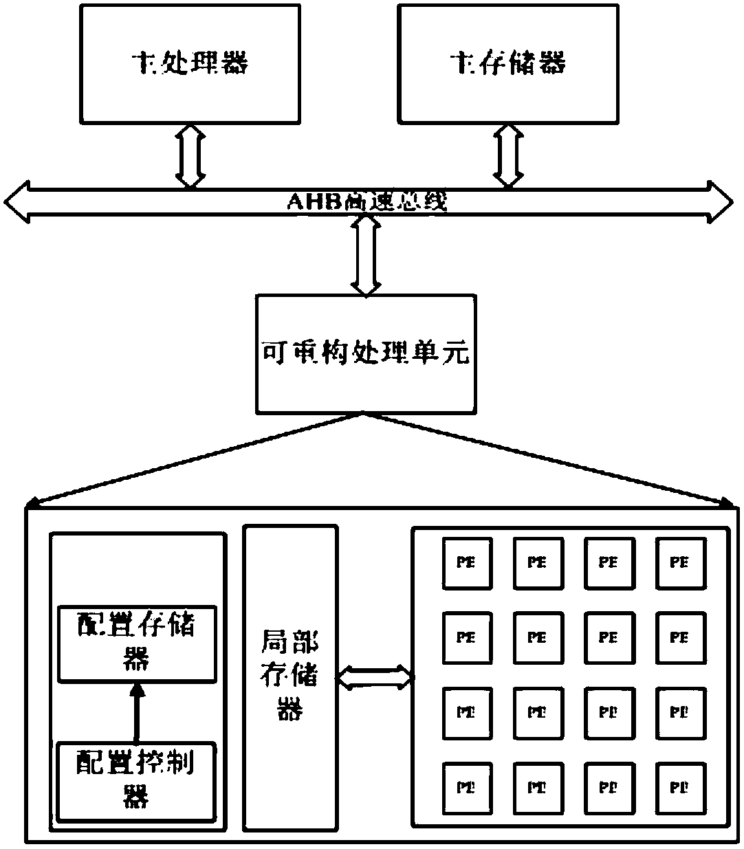
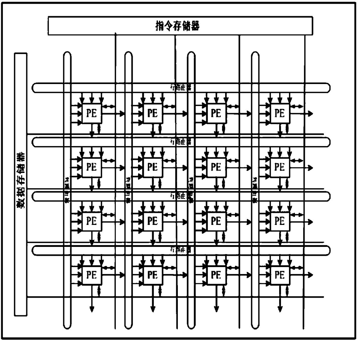

Image

  • A multi-objective optimization automatic mapping scheduling method for row-column parallel coarse-grained reconfigurable arrays
  • A multi-objective optimization automatic mapping scheduling method for row-column parallel coarse-grained reconfigurable arrays
  • A multi-objective optimization automatic mapping scheduling method for row-column parallel coarse-grained reconfigurable arrays

Examples


specific example

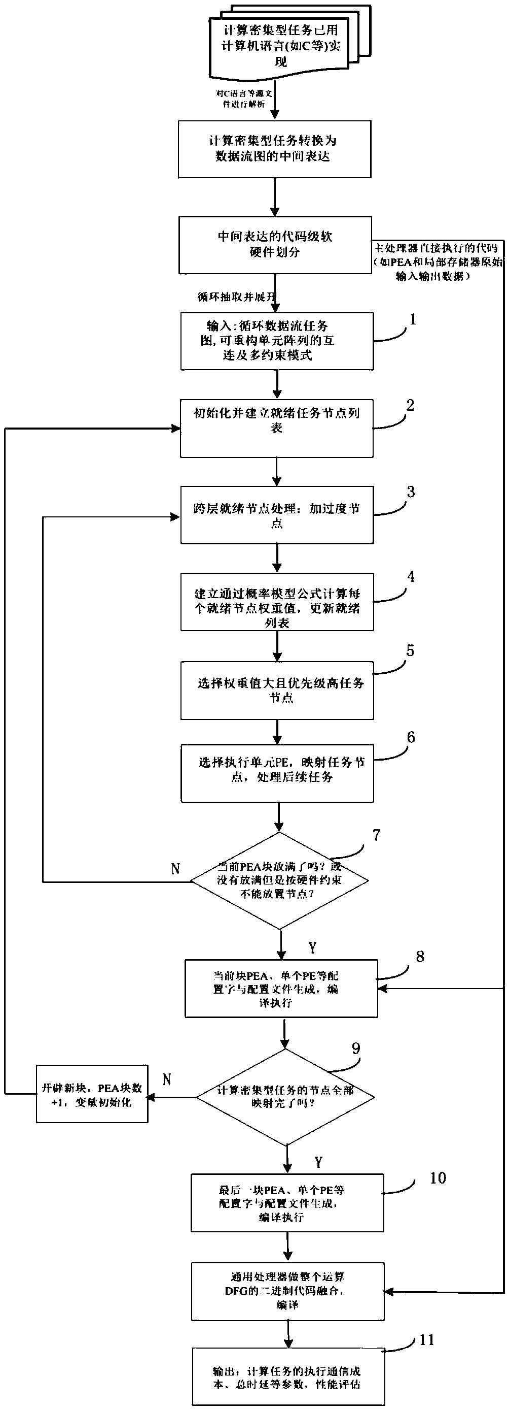
[0051] see image 3 The flow of a multi-objective optimization automatic mapping and scheduling method for row-column parallel coarse-grained reconfigurable arrays, combined with specific examples, specifically includes the following steps:

[0052] Preprocessing step: Computation-intensive tasks have been implemented in high-level languages ​​such as C language, and source files such as C language are parsed and extracted, and converted into intermediate expressions of data flow graph DFG, and code-level software and hardware division of intermediate expressions is performed : The software part of the main processor: the original input and output of the calculation task, which needs to be stored or read through the PEA and the local memory, and the code is directly controlled and executed by the main processor; the hardware array part of the PEA: the key loop for obtaining the calculation-intensive task Intermediate expression of the DFG, which unrolls the cyclic DFG.

[005...


PUM


Abstract

The invention discloses a method for multi-objective optimization automatic map scheduling of row-column parallel coarse-grained reconfigurable arrays. Computing-intensive tasks are described in codesuch as C, which is translated into an intermediate representation of the data flow graph by semantic parsing, and then hardware and software are divided at the code level, the platform information such as the interconnection of the reconfigurable cell arrays and the scale constraint and the task set of the reconfigurable data flow are inputted through the core loop tool software to initialize theready task queue, the ready cross-layer and misaligned tasks are then removed, the priority of the operation nodes is calculated, and the execution units are selected to map one by one. The scenariois based on tightness dependencies between task nodes, a solution is given under the conditions of the parallelism of task nodes, which effectively solves the problems of high communication cost between computing arrays, ineffective integration of execution time extension and task scheduling in traditional methods, and achieves higher acceleration ratio, lower configuration cost and higher resource utilization ratio of reconfigurable units.

Description

technical field [0001] The invention relates to the field of computer architecture, in particular to a task probability calculation and mapping scheduling method for a row-column task parallel coarse-grained reconfigurable platform. Background technique [0002] The computing mode of traditional general-purpose processors has the advantages of programmability and flexibility, but for computing-intensive tasks with a large number of cycles, such as multimedia computing, graphic image computing or processing, the processing speed is relatively slow; integrated circuit (ASIC) has the advantages of fast computing speed, but has the disadvantages of specificity and inflexibility; the reconfigurable computing platform combines the advantages of both general-purpose processors and ASIC computing modes, and has both flexible programming and high computing power. Speed ​​and other advantages, the reconfigurable computing structure can realize the pipeline or non-pipeline operation of...

Claims


Application Information

Patent Timeline
IPC IPC(8): G06F9/48
CPCG06F9/4881
Inventor 陈彦楠
Owner LANZHOU UNIVERSITY
Learn More