
Steam generator blowdown apparatus

A steam generator and sewage device technology, applied in the chemical industry, can solve the problems of continuous impact on the bottom of the sewage pipe, uneven distribution, inability to inhale and discharge sewage, or even accumulation.

Active Publication Date: 2018-12-18
HUAIYIN INSTITUTE OF TECHNOLOGY +1
View PDF8 Cites 2 Cited by
  • Summary
  • Abstract
  • Description
  • Claims
  • Application Information

AI Technical Summary

Problems solved by technology

[0005] Some problems will appear in the practical application of the existing sulfuric acid steam generator blowdown device, which will affect the blowdown effect and equipment work efficiency:
[0006] 1. The existing sewage discharge device only relies on one sewage discharge pipe to discharge sewage, and the sewage suction pipe is distributed in a straight line on the sewage discharge pipe. The effective sewage discharge area is small and unevenly distributed, resulting in the inability of timely and efficient suction and discharge of distant sewage or even accumulation;
[0007] 2. In the area near the straight line where the sewage suction pipe is located, because the sewage is discharged quickly, a part of the non-pollution liquid will be filled up, so that the non-pollution liquid that does not need to be discharged will be discharged;
[0008] 3. Several sewage suction pipes are connected to the same sewage pipe, once the sewage pipe is damaged, the whole device will be affected;
[0009] 4. Long-term sewage falling from the mouth of the sewage suction pipe to the bottom of the sewage pipe will cause continuous impact on the bottom of the sewage pipe and affect the life of the sewage pipe

Method used

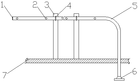

Image

  • Steam generator blowdown apparatus
  • Steam generator blowdown apparatus
  • Steam generator blowdown apparatus

Examples


Embodiment approach 1

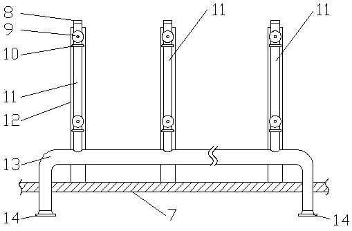
[0037] This embodiment provides a blowdown device for a steam generator, which consists of a main blowdown pipe 13, a number of secondary blowdown pipes 11, and a number of suction heads 9 arranged on each secondary blowdown pipe 11, the number of secondary blowdown pipes 11 and The number of sewage suction heads 9 on each auxiliary sewage pipe 11 is determined by the liquid level in the steam generator; for the convenience of description, the following descriptions use a main sewage pipe 13 to connect three auxiliary sewage pipes 11, each auxiliary sewage pipe There are two dirt suction heads 9 on 11 for description. Such as image 3 As shown, three secondary sewage pipes 11 are connected in parallel on a main sewage pipe 13, and the diameter of the secondary sewage pipes 11 is slightly smaller than the diameter of the main sewage pipe 13, so that the sewage collected by the secondary sewage pipes 11 has sufficient space in the main sewage pipe 13. Flow space; the distance b...

Embodiment approach 2

[0042] This embodiment is a further improvement of Embodiment 1. The main improvement is that in Embodiment 1, sewage will be diverted when it enters the sewage suction chamber 20 through the sewage suction narrow channel 19, and a small part of it will flow along the sewage suction chamber 20. The wall flows down, and most of them flow down vertically through the sewage suction narrow channel 19 and impact the bottom of the sewage suction chamber 20, and impact the lower pipe wall of the auxiliary sewage pipe 11 at a relatively high speed, which greatly affects the life of the auxiliary sewage pipe 11; In this way, the above-mentioned defects can be effectively avoided.

[0043] Specifically, in the sewage discharge device of the steam generator in this embodiment, the sewage suction head 9 also includes a blocking cap 21 structure, and the structure of the blocking cap 21 is as follows: Figure 9~11 As shown, the upper part is an arc-shaped housing 16 extending into the dirt...

Embodiment approach 3

[0047] This embodiment is a further improvement of Embodiment 2. The main improvement is that in Embodiment 2, the arc-shaped outer wall of the auxiliary sewage pipe 11 is in line contact with the plane of the T-shaped steel 12, and the pressure is relatively high, which is easy to cause The device is unstable, and the height difference between the auxiliary sewage pipe 11 and the main sewage pipe 13 due to the different diameters will also affect the stability of the device. In this embodiment, however, the above defects can be effectively avoided.

[0048] Specifically, in this embodiment, a saddle-shaped block 26 is placed between the auxiliary sewage pipe 11 and the T-shaped steel, and inside the U-shaped bolt 10, as Figure 12 with 13 , the lower surface of the saddle block 26 is a plane in contact with the T-shaped steel 12, and the upper surface is a concave arc surface that fits the lower part of the auxiliary sewage pipe 11. On the one hand, the saddle block 26 can ...


PUM


Abstract

The invention relates to the field of chemical engineering, and discloses a steam generator blowdown apparatus. A plurality of auxiliary blow-off pipes (11) communicate with a main blow-off pipe (13)in a parallel connection mode. Each auxiliary blow-off pipe is provided with at least one pollutant absorption head (9). All the auxiliary blow-off pipes (11) are detachably fixed to T-shaped steel parts (12), and all the T-shaped steel parts are fixed to an inner side wall (7) of a steam generator. Each pollutant absorption head is in the shape of a gourd with a horn opening on the whole and is mainly composed of a horn-shaped pollutant absorption opening (18), a pollutant absorption narrow path (19), a loudbelly-shaped pollutant absorption cavity (20) and a threaded connector (23) which arein seamless connection in sequence. All the auxiliary blow-off pipes communicate with the pollutant absorption heads through pollutant absorption head connectors (24). One ends of the pollutant absorption head connectors are fixedly connected with the auxiliary blow-off pipes, and the other ends of the pollutant absorption head connectors are connected with the threaded connectors in a threaded mode. Compared with the prior art, the steam generator blowdown apparatus is even, reliable and efficient in pollutant discharging, discharging of non-dirty liquid can be effectively avoided, and the service life of the blow-off pipes is effectively prolonged.

Description

technical field [0001] The invention relates to the field of chemical industry, in particular to a blowdown device for a steam generator. Background technique [0002] Sulfuric acid is an extremely important chemical raw material. The production of sulfuric acid mainly includes the combustion of sulfur-containing raw materials, the oxidation of sulfur dioxide and the absorption of sulfur trioxide. The absorption of sulfur trioxide with concentrated sulfuric acid is an important means of sulfuric acid production. The absorption of sulfur trioxide is an exothermic reaction, and the heat released per ton of sulfuric acid during the absorption process reaches 319KCAL / T. If the heat can be recovered and utilized, it will bring huge economic benefits. In the sulfuric acid industry, no matter whether pyrite is used to make acid, or sulfur and smelting gas are used to make acid, a large amount of waste heat is generated in the production process, and the high and medium temperature ...

Claims


Application Information

Patent Timeline
Patent Type & Authority Applications(China)
IPC IPC(8): F22B37/54
CPCF22B37/54
Inventor 黄梓庭李伯奎汤鹏江振飞宋泽康周靖滑小彤王在良
Owner HUAIYIN INSTITUTE OF TECHNOLOGY
Learn More