a composite machine
A composite machine and pre-compound technology, applied in lamination, chemical instruments and methods, lamination auxiliary operations, etc., to achieve high efficiency, ensure flatness, and improve the scope of application
- Summary
- Abstract
- Description
- Claims
- Application Information
AI Technical Summary
Problems solved by technology
Method used
Image
Examples
Embodiment 1
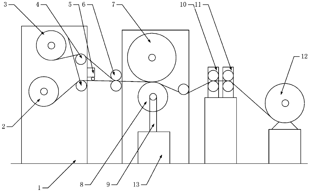
[0024] A kind of novel compound machine described in the present invention, as figure 1 As shown, it includes frame 1, first unwinding device 2, second unwinding device 3, tensioning device 4, electrostatic generator 5, pre-compositing device 6, composite steel roller 7, pressing steel roller 8, linear guide rail 9. Guide device 10, traction device 11, winding device 12, central controller 13. The first unwinding device 2, the second unwinding device 3, the tensioning device 4, the electrostatic generator 5, the pre-composite device 6, the composite steel roller 7, the pressing steel roller 8, the linear guide rail 9, the guide device 10, The traction device 11, the winding device 12, and the central controller 13 are fixed on the frame 1, and the first unwinding device 2 and the second unwinding device 3 are arranged at the front end of the frame 1, and all pass through the tensioning device 4 To realize the tension of the raw material, the first unwinding device 2 is provid...
Embodiment 2
[0028] a kind of like figure 1 The new composite machine shown is used for the production of special materials, and the workflow is:
[0029] Step 1. Load the two raw materials that need to be compounded into the unwinding device. The main raw material is loaded into the first unwinding device. The main raw material is an asymmetric graphene oxide polyimide hollow fiber membrane, and the auxiliary raw material is loaded into the second Unwinding device, auxiliary raw materials include but not limited to: metal foil, rubber, non-woven fabric, PE film, special fiber, paper products, film, etc.;
[0030] Step 2. Adjust the tensioning device so that the two raw materials are in a tensioned state after passing through the tensioning device. Among them, when the main raw material passes through the electrostatic generator, the electrostatic generator works under the control of the central processing unit, and the wire electrode wheel rotates and stretches. The electrode wire comes ...
Embodiment 3
[0035]Graphene oxide (GO) aqueous suspension was prepared by the modified Hummers method, using flake graphite powder as the starting material, the resulting GO aqueous suspension was sonicated for 30 min, and then centrifuged at 8000 rpm for 30 min to remove incomplete oxidation of graphite. GO powder was obtained by freeze-drying overnight to prepare asymmetric graphene oxide polyimide hollow fiber membranes, specifically, 0.72 g GO powder was dispersed in 50 mL of methylpyrrolidone gel and stirred vigorously for 10 min, followed by ultrasonic treatment for 1 h , then add 10g of polyimide to the methylpyrrolidone gel and stir vigorously at 75°C, then add 1.5g of polyvinylpyrrolidone to it, then stir at 75°C for 2 hours to form a raw material solution, and put the raw material solution into Vacuum pump, under the action of vacuum pump, carry out vacuum dehydration, cast through the casting manufacturing device of screw strong pressure conveying, melt the raw materials, and th...
PUM
 Abstract
Description
Claims
Application Information
 - R&D Engineer
- R&D Manager
- IP Professional
- Industry Leading Data Capabilities
- Powerful AI technology
- Patent DNA Extraction
Browse by: Latest US Patents, China's latest patents, Technical Efficacy Thesaurus, Application Domain, Technology Topic, Popular Technical Reports.
© 2024 PatSnap. All rights reserved.Legal|Privacy policy|Modern Slavery Act Transparency Statement|Sitemap|About US| Contact US: help@patsnap.com


