Light guiding assembly and manufacturing method thereof, eyeball tracking module and method thereof and video glasses
A light guide component and eye tracking technology, applied in the field of human-computer interaction, can solve the problems that eye tracking modules cannot be controlled in real time, occupy a large volume, and cannot meet the needs of thinning eye tracking modules.
- Summary
- Abstract
- Description
- Claims
- Application Information
AI Technical Summary
Problems solved by technology
Method used
Image
Examples
Embodiment 1
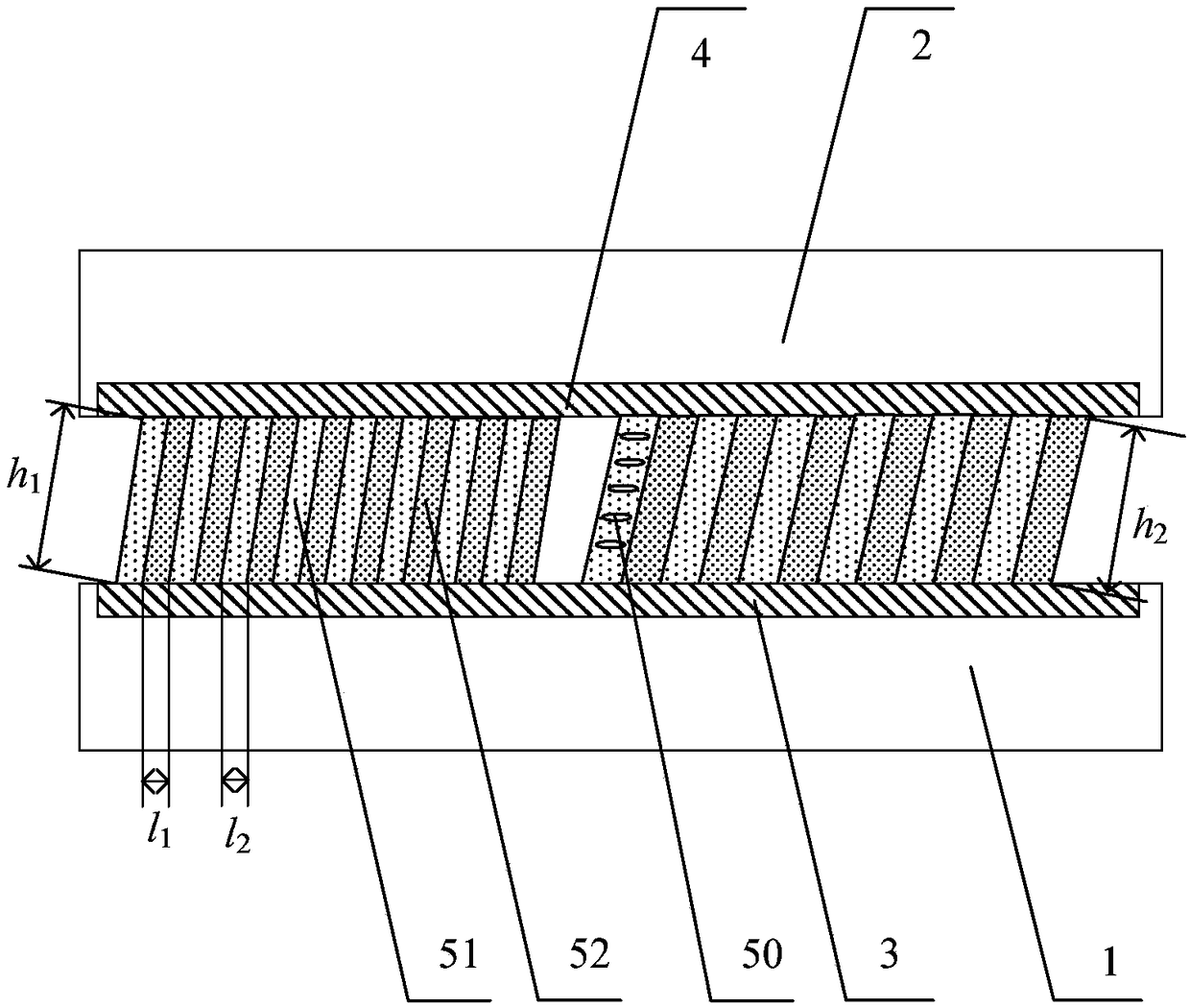
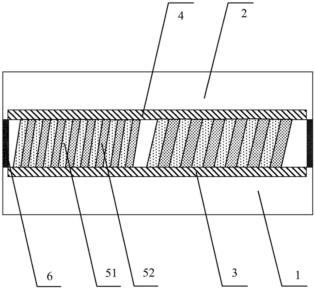
[0070] figure 1 Schematic diagram of the structure of the light guide assembly provided for the embodiment of the present invention Figure 1 ,Such as figure 1 As shown, the light guide assembly provided by the embodiment of the present invention is set in the eye tracking module, and includes: a first substrate 1 and a second substrate 2 oppositely arranged, a first electrode 3 arranged on the first substrate 1, a set The second electrode 4 on the second substrate 2 and at least one liquid crystal structure 5 disposed between the first electrode 3 and the second electrode 4, the liquid crystal structure 5 includes liquid crystal molecules (not shown in the figure).
[0071] Wherein, the first electrode 3 and the second electrode 4 are used to control the deflection direction of the liquid crystal molecules through the applied voltage, so that the light directed to the light guide assembly meeting the threshold condition is emitted along a predetermined direction.
[0072] I...
Embodiment 2
[0102] Based on the inventive concepts of the foregoing embodiments, Figure 5 A schematic structural diagram of the eye tracking module provided for the embodiment of the present invention, such as Figure 5 As shown, the embodiment of the present invention also provides an eye tracking module, which is set in the video glasses, wherein the eye tracking module includes: a transmitting component 10, a light guiding component 20, a receiving component 30 and a main control component (not shown in the figure) show).
[0103] Specifically, the emitting component 10 is used to emit invisible light to the light guide component 20; the light guide component 20 is used to emit the invisible light directed to the light guide component along a predetermined direction; the receiving component 30 is used to receive the non-visible light reflected by the eyeball. Visible light generates electrical signals under the irradiation of invisible light; the main control component is used to rec...
Embodiment 3
[0144] Based on the above examples, Figure 8 The flow chart of the manufacturing method of the light guide assembly provided by the embodiment of the present invention, such as Figure 8 As shown, the manufacturing method of the light guide assembly provided by the embodiment of the present invention specifically includes the following steps:
[0145] Step S100 , providing a first substrate, and forming a first electrode on the first substrate.
[0146] Optionally, the material for making the first substrate may be glass, plastic, or polyimide, which is not limited in this embodiment of the present invention.
[0147] Specifically, forming the first electrode on the first substrate includes: forming a groove on the first substrate through a laser process or a photolithography process, depositing a transparent conductive film in the groove, and processing the transparent conductive film through a patterning process to form a second electrode. an electrode.
[0148] Optional...
PUM
| Property | Measurement | Unit |
|---|---|---|
| Wavelength | aaaaa | aaaaa |
Abstract
Description
Claims
Application Information
 - R&D
- Intellectual Property
- Life Sciences
- Materials
- Tech Scout
- Unparalleled Data Quality
- Higher Quality Content
- 60% Fewer Hallucinations
Browse by: Latest US Patents, China's latest patents, Technical Efficacy Thesaurus, Application Domain, Technology Topic, Popular Technical Reports.
© 2025 PatSnap. All rights reserved.Legal|Privacy policy|Modern Slavery Act Transparency Statement|Sitemap|About US| Contact US: help@patsnap.com


