Water-separating system of wellhead produced object and water-separating treatment method

A water phase and dissolved gas water technology, which is applied in the direction of production fluid, earthwork drilling, wellbore/well components, etc., can solve the problem of large area occupied by the subsequent coalescence degreaser and poor oil, gas and water three-phase separation effect , The three-phase separator occupies a large area, etc., to achieve the effect of reducing the occupied area and space volume, large processing load, and large buffer coefficient

Pending Publication Date: 2018-12-11
宁波信意达油气技术合伙企业(有限合伙)
View PDF0 Cites 4 Cited by
  • Summary
  • Abstract
  • Description
  • Claims
  • Application Information

AI Technical Summary

Problems solved by technology

[0002] During the production of oil and gas fields, with the increase of the production period, the water content in the wellhead production will increase significantly, making the production capacity of the wellhead equipment insufficient, and this part of the water usually directly enters the oil-gas-water three-phase separation system after production. As a result, the three-phase separation effect of oil, gas and water becomes poor.
Due to the existence of produced water, the economic investment in the equipment along the process is relatively large. If part of the water cannot be removed at the wellhead, the economic investment in the back-end equipment will be large and the output will be low. The waste is firstly subjected to water separation treatment and reaches the sea discharge index requirement of 30ppm
There are many kinds of water separation treatment methods for the existing wellhead produced materials, such as "traditional three-phase separator + hydrocyclone + coalescence degreaser". It occupies a large area and has a low water separation rate. It occupies a larger area than the compact air flotation device after the coalescing degreaser, and the separation and degreasing efficiency of the coalescing packing is low.

Method used


Image

  • Water-separating system of wellhead produced object and water-separating treatment method

Examples


specific Embodiment 1

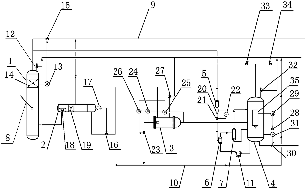
[0030] A water separation system for wellhead production, such as figure 1 As shown, it includes a columnar cyclone separator 1, a high-efficiency horizontal separator 2, a hydrocyclone 3, an air flotation tank 4, a gas filter 5, a gas injector 6, and a nano-scale microbubble generator 7. The columnar cyclone The middle part of the separator 1 is provided with a wellhead production inlet pipe 8, and the bottom liquid phase outlet of the columnar cyclone separator 1 is connected with the bottom liquid phase inlet of the high-efficiency horizontal separator 2; the top oil phase of the high-efficiency horizontal separator 2 The outlet is connected to the export pipeline 9 for crude oil export, the bottom water phase outlet of the high-efficiency horizontal separator 2 is connected to the tangential inlet of the hydrocyclone 3; the oil phase outlet of the hydrocyclone 3 is connected to the sewage sink Pipe 10, the tail water phase outlet of the hydrocyclone 3 is connected to the m...

specific Embodiment 2

[0036] A method of using the water separation system described in the above specific embodiment 1 to carry out water separation treatment of wellhead produced materials, such as figure 1 shown, including the following steps:

[0037] (1) Send the oil, gas and water three-phase wellhead production through the wellhead production inlet pipe 8 into the columnar cyclone 1, and control the temperature in the columnar cyclone 1 to 60-99°C and the pressure to 1.1 -35MPaG, at the same time, under the action of swirling flow, centrifugal force, gravity and buoyancy form an inverted conical vortex surface, the liquid phase with high density flows along the pipe wall of the vertical pipe to the bottom of the columnar cyclone separator, and the gas phase with low density Rise to the vortex surface along the center of the vortex and flow to the top of the columnar cyclone separator 1, and the separated gas phase is directly used as the gas source of the air flotation tank 4;

[0038] (2) ...


PUM


Abstract

The invention discloses a water-separating system of a wellhead produced object and a water-separating treatment method thereof. The system is characterized by comprising a columnar cyclone separator,an efficient horizontal separator, a hydrocyclone, and an air floating tank. An oil receiving cylinder arranged in the air floating tank is connected with a pollution discharge header. An aqueous outlet on the bottom of the air floating tank is connected with open seas or a wellhead injection inlet. A top gas outlet of the columnar cyclone separator is connected with an air source injection portof a gas injector through a gas filter. A microbubble gas-dissolved water outlet of the gas injector is connected with a nano microbubble preparation device. A top nano microbubble gas-dissolved wateroutlet of the nano microbubble preparation device is connected with an upper part inlet of the air floating tank. A bottom water outlet of the nano microbubble preparation device is connected with alower part inlet of the air floating tank. The bottom of the air floating tank is connected with a bottom water inlet of the gas injector through a circulating pump. The water-separating system is advantaged by realizing direct water separation of wellhead produced objects and discharging standardized, and oil-gas products after water separation can directly return to an original outer transportation pipeline.

Description

technical field [0001] The invention relates to a water separation system and a water separation treatment method for wellhead produced materials. Background technique [0002] During the production of oil and gas fields, with the increase of the production period, the water content in the wellhead production will increase significantly, making the production capacity of the wellhead equipment insufficient, and this part of the water usually directly enters the oil-gas-water three-phase separation system after production. As a result, the three-phase separation effect of oil, gas and water is deteriorated. Due to the existence of produced water, the economic investment in the equipment along the process is relatively large. If part of the water cannot be removed at the wellhead, the economic investment in the back-end equipment will be large and the output will be low. The waste is firstly subjected to water separation treatment, and reaches the sea discharge index requirem...

Claims


Application Information

Patent Timeline
Patent Type & Authority Applications(China)
IPC IPC(8): E21B43/34
CPCE21B43/34
Inventor 章志松王敏谷松冯福祥曲书进薛亮亮陈龙俊戴科波刘科杰江宏亮冯明鑫王斌冯吉祥陈国发张西亮庞日彪李雪梅冯晓凤郝贺杰曹岩辉
Owner 宁波信意达油气技术合伙企业(有限合伙)
Why Eureka
Try Eureka