
Hydrogen generator

A generator and hydrogen technology, applied in the field of laboratory equipment, can solve the problems of unfavorable experimental efficiency, large hydrogen consumption, high instrument failure rate, etc., and achieve the effect of improving experimental efficiency

Active Publication Date: 2018-12-07
GREENTOWN AGRI TESTING TECH CO LTD +1
View PDF10 Cites 0 Cited by
  • Summary
  • Abstract
  • Description
  • Claims
  • Application Information

AI Technical Summary

Problems solved by technology

[0004] In the existing hydrogen generators in large-scale laboratories, one hydrogen generator often supplies hydrogen to 3-4 gas chromatographs at the same time, and the hydrogen consumption is relatively large. During daily use, experimenters need to regularly add electrolytic Liquid, on the one hand, the failure rate of the instrument is often caused by the delay in adding electrolyte, on the other hand, it will cause the experimenter to be distracted, which is not conducive to improving the efficiency of the experiment

Method used


Image

  • Hydrogen generator
  • Hydrogen generator
  • Hydrogen generator

Examples


Embodiment Construction

[0029] This embodiment provides a technical solution:

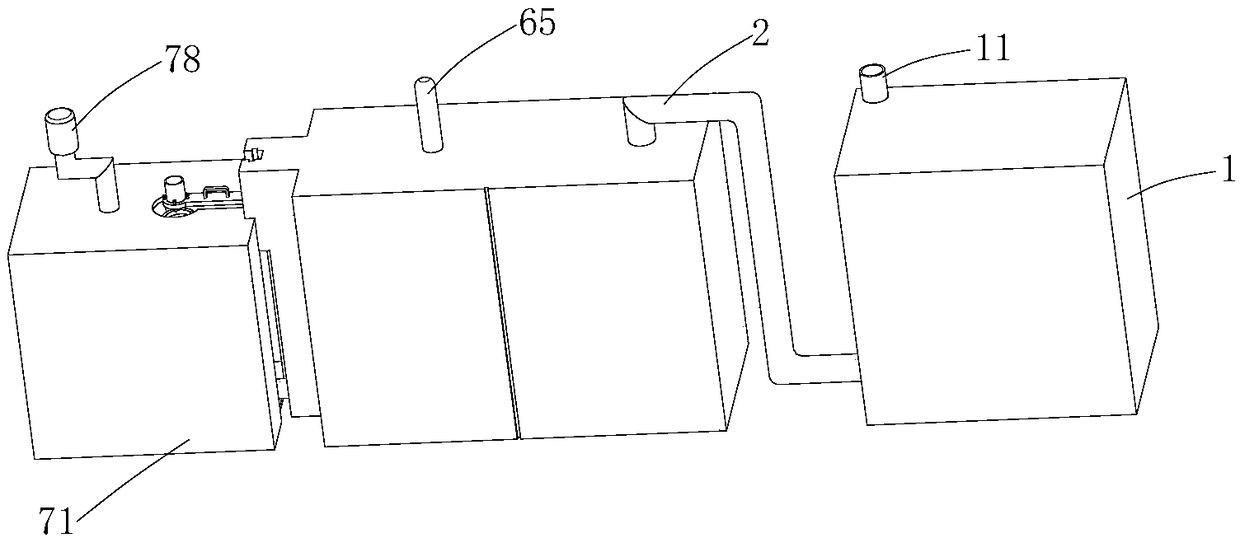
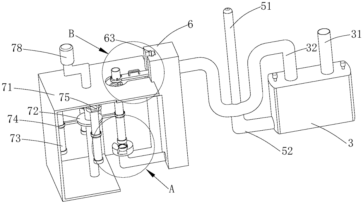
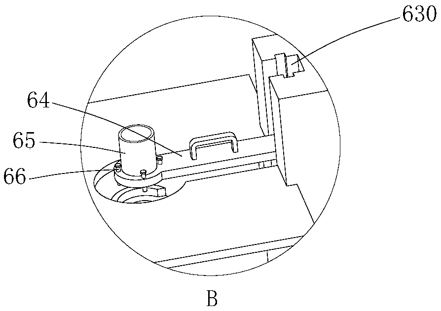
[0030] Such as Figure 1-9 As shown, a hydrogen generator includes a liquid storage tank 1 for storing electrolyte, an electrolysis device 3, a first connecting pipe 2, and a water removal device for removing water vapor entrained in hydrogen; the electrolysis device 3 includes a hollow The housing, the hydrogen outlet pipe 32 sleeved on the negative electrode and the oxygen outlet pipe 31 sleeved on the positive electrode, the oxygen outlet pipe 31 communicates with one end of the first connecting pipe 2, the liquid storage tank 1 and the first connecting pipe 2 One end facing away from the oxygen outlet pipe 31 is connected, and the liquid storage tank 1 is provided with an oxygen discharge pipe 11 for discharging oxygen; The inner side wall of the tank is provided with a ventilation groove for supplying oxygen into the liquid storage tank 1.

[0031] Such as Figure 8 As shown, the pressure opening and closing valve...


PUM


Abstract

The invention discloses a hydrogen generator, and particularly relates to a laboratory device. The hydrogen generator comprises a solution storage tank used for storing an electrolyte solution, an electrolytic device, a first connecting pipe and a water removal device for removing water vapor entrained in hydrogen; the electrolytic device comprises a hollow shell, a hydrogen outlet pipe arranged on a negative pole in a sleeving mode, and an oxygen outlet pipe arranged on a positive pole in a sleeving mode; the oxygen outlet pipe communicates with one end of the first connecting pipe, the solution storage tank communicates with the end, deviating from the oxygen outlet pipe, of the first connecting pipe; the solution storage tank is provided with an oxygen exhausting pipe for exhausting oxygen; the first connecting pipe is provided with a pressure opening and closing valve which is opened along with decreasing of the oxygen pressure; and an oxygen injecting groove for allowing the oxygen to be injected into the solution storage tank is formed in the inner side wall of the first connecting pipe. When the hydrogen generator works, the advantage of automatic addition of the electrolytesolution can be achieved if the amount of the internal electrolyte solution is insufficient.

Description

technical field [0001] The invention relates to a laboratory instrument, in particular to a hydrogen generator. Background technique [0002] Gas chromatograph analysis refers to the technology of using gas as mobile phase to realize the separation of compounds by using the differences in boiling point, polarity and adsorption properties of substances. The detectors that are often equipped are hydrogen flame ionization detector (GC-FID), flame photometric detector (FPD), nitrogen phosphorus detector (NPD) and so on. This type of detector needs to chemically ionize the compound under the action of a hydrogen flame to form an ion flow or burn in a hydrogen-rich flame to emit a characteristic spectrum, thereby generating a signal for detection and analysis. [0003] At present, the source of combustion gas hydrogen is mainly provided by cylinder gas or hydrogen generator, cylinder hydrogen is expensive and inconvenient to use and replace, hydrogen is easily produced by ionized...

Claims


Application Information

Patent Timeline
IPC IPC(8): C25B1/04C25B15/08
CPCC25B1/04C25B15/08Y02E60/36
Inventor 朱萌萌胡松周敏周婷婷李樱红王川丕刘小羽俞璐萍黎斌
Owner GREENTOWN AGRI TESTING TECH CO LTD
Learn More