


Quick Research
Generate reliable direction feasibility study reports for your R&D in just a few steps.

Technical Q&A
Discover and master advanced knowledge NOW. Basics, ideas, possibilities, all at once.

Find Solutions
As an expert in R&D theories, this can generate solutions to your technical problems instantly.

Evaluate Feasibility
Analyze your overall solution with one click, know your potential R&D risks in advance.

Monitor Landscape
Get weekly tech updates, stay abreast of the latest tech innovations and key insights.
A method for removing the cap layer in the preparation of SIC nanostructures by anodic oxidation
A nanostructure and anodizing technology, applied in the field of materials, can solve the problems of reduced pore openness, existence of cap layer structure, functional application obstacles, etc., to achieve the effect of improving openness, improving performance, and shortening etching time
- Summary
- Abstract
- Description
- Claims
- Application Information
AI Technical Summary
Problems solved by technology
Method used
Image

Examples
Embodiment 1
[0035] Weigh 13g NH 4 HF 2 Dissolve the powder in 20mL deionized water, and make it saturated with NH 4 HF 2 solution.
[0036] The etching solution is prepared by mixing hydrofluoric acid, ethanol and hydrogen peroxide solution in a volume ratio of 3:6:1.
[0037] Cut the industrial-grade SiC wafer into small pieces with a size of 0.7×1.5 cm, and ultrasonically clean them in alcohol and deionized water for 10 min respectively, and place the cleaned SiC wafer in an ethanol solution containing HF acid (the volume ratio of HF to ethanol is 2: 1) soak for 2 minutes, take it out and dry it in a 40°C oven for 10 minutes.
[0038] Clamp the cleaned and dried 4H-SiC wafer on the motor clamp, connect the positive electrode of the pulse power supply, as the anode of the experiment, connect the carbon plate to the negative electrode of the pulse power supply, and use it as the cathode of the experiment, set the constant current mode of the pulse power supply, and the current density...
Embodiment 2
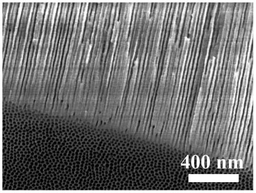
[0042] The difference from Example 1 is that the etching solution in Example 2 is prepared by mixing hydrofluoric acid, ethanol and hydrogen peroxide in a volume ratio of 6:6:1, and the others are the same as in Example 1, and will not be repeated here. stated. The SEM figure of the SiC nanostructure that this embodiment makes is Figure 4 As shown, it shows that the prepared SiC nanostructure is a SiC nanopore structure with completely open pores, and there is no cap layer structure on the surface. Further, the cap layer caused by the original anodic oxidation is removed in this embodiment, and this embodiment engraved No new cap layer is formed during the erosion process.
Embodiment 3
[0044] The difference from Example 1 is that the etching solution in this example is prepared by mixing hydrofluoric acid, ethanol and hydrogen peroxide solution in a volume ratio of 2:6:1, and the others are the same as in Example 1, and will not be repeated here. .
PUM
 Abstract
Description
Claims
Application Information
 - R&D Engineer
- R&D Manager
- IP Professional
- Industry Leading Data Capabilities
- Powerful AI technology
- Patent DNA Extraction
Browse by: Latest US Patents, China's latest patents, Technical Efficacy Thesaurus, Application Domain, Technology Topic, Popular Technical Reports.
© 2024 PatSnap. All rights reserved.Legal|Privacy policy|Modern Slavery Act Transparency Statement|Sitemap|About US| Contact US: help@patsnap.com